Geological hazard early-warning and monitoring device

A technology for early warning monitoring and geological disasters, applied in measuring devices, alarms, rainfall/precipitation gauges, etc., can solve the problems of inability to comprehensively monitor, single, and geological disaster early warning monitoring devices without multi-level early warnings, etc.

Inactive Publication Date: 2019-12-20
HUAIYIN TEACHERS COLLEGE
View PDF7 Cites 8 Cited by
  • Summary
  • Abstract
  • Description
  • Claims
  • Application Information

AI Technical Summary

Problems solved by technology

[0003] The existing early warning and monitoring devices for geological disasters do not...

Method used


Image

  • Geological hazard early-warning and monitoring device
  • Geological hazard early-warning and monitoring device
  • Geological hazard early-warning and monitoring device

Examples


Embodiment 1

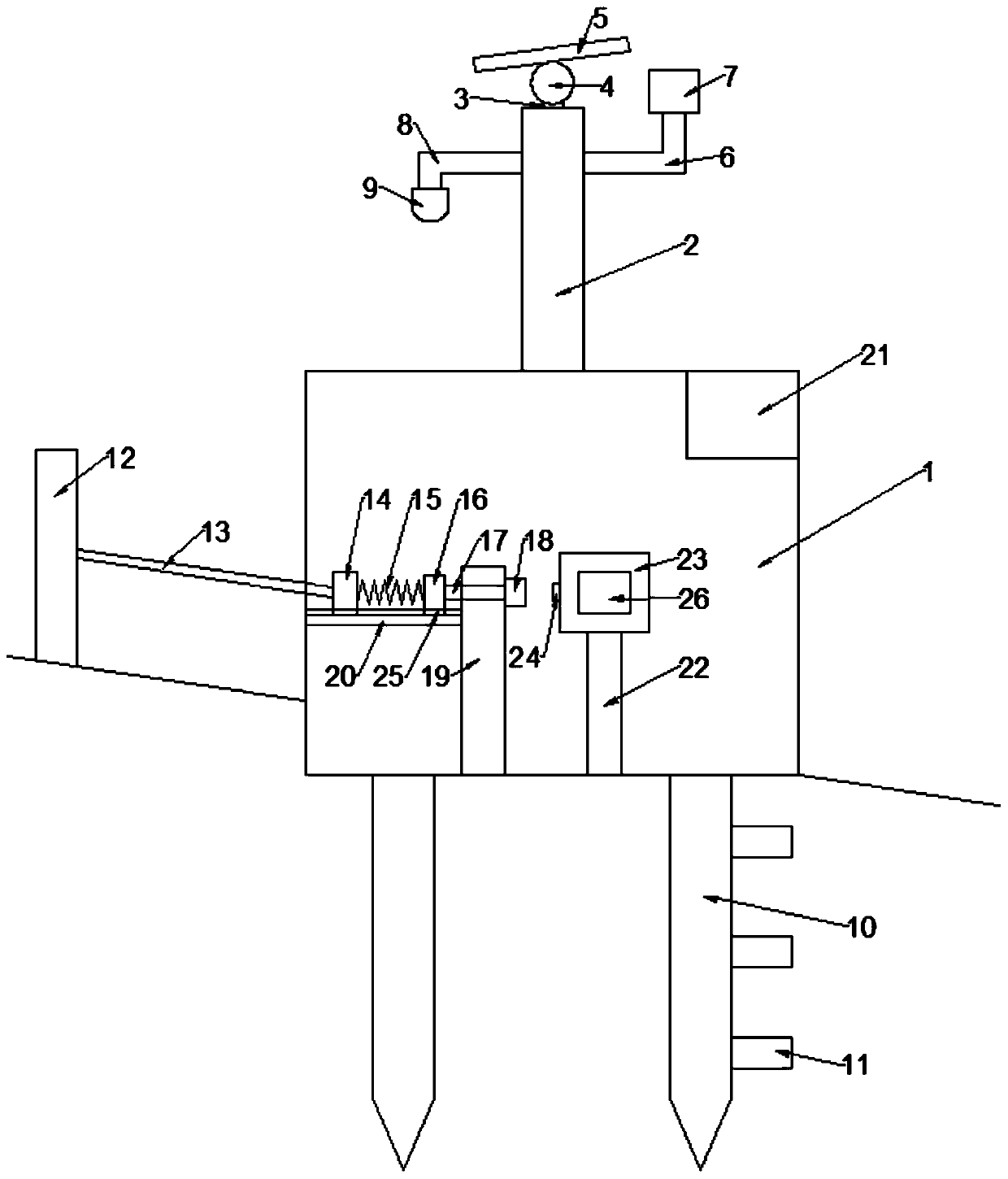
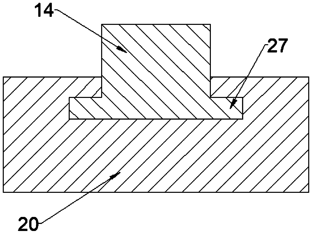
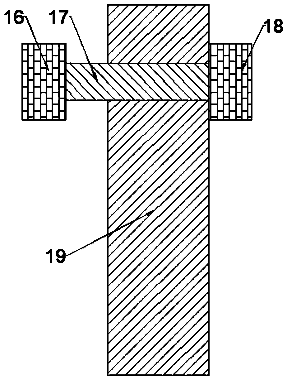
[0022] See Figure 1-4 , An early warning and monitoring device for geological disasters, comprising a housing 1, a cavity is provided in the housing 1, a supporting column 2 is installed on the top, a rotating shaft 3 is provided on the top of the supporting column 2, and a rotating rod 4 is rotatably connected to the rotating shaft 3. The solar panel 5 is connected to the 4, and the rotating rod 4 can drive the solar panel 5 to rotate on the rotating shaft 3, so that the solar panel 5 always faces the sun and improves the utilization rate of solar energy. A connecting rod 6 is provided on the side of the support column 2 The connecting rod 6 is in an inverted "L" shape. The horizontal rod body of the connecting rod 6 is fixedly connected to the side wall of the support column 2, and the vertical rod body is fixedly connected to the rain gauge 7 and facing upwards. The rain gauge 7 can measure and record For the amount of precipitation in this place, the other side of the supp...

Embodiment 2

[0031] In order to prevent the monitoring device from running out of power when there is no sun, this embodiment is further improved on the basis of embodiment 1. The improvement is that a storage battery 21 is provided in the casing 1, and the storage battery 21 can store the electric energy converted by the solar panel 5 When it is cloudy, the battery 21 can provide electrical energy to ensure the normal operation of the monitoring device.

[0032] The working principle of this embodiment is: the monitoring device can maintain operation through the solar panel 5 to provide electrical energy. When there is a long-term cloudy rainstorm here, the solar panel 5 cannot convert solar energy to provide electrical energy. The battery 21 is installed in the monitoring device to ensure The monitoring device can also operate normally when there is no sun, and the battery 21 can also store the excess electric energy converted by the solar panel 5 for emergency needs.

[0033] To sum up, by s...


PUM


Abstract

The invention discloses a geological hazard early-warning and monitoring device. The device includes an outer housing. A cavity is arranged in the outer housing. A support column is mounted at a top.A first connecting rod is arranged at one side of the support column. A horizontal rod body of the first connecting rod is fixedly connected to a side wall of the support column, and a vertical rod body is fixedly connected with a rain gauge and faces upward. A second connecting rod is arranged on the other side of the support column, and shows an inverted "L" shape. A horizontal rod body of the second connecting rod is fixedly connected to the side wall of the support column, and a vertical rod body is fixedly connected with a camera and faces downward. Fixing rods buried under the ground arearranged at a lower end of the outer housing. Multiple soil moisture sensors are arranged from tops to bottoms on outside walls of the fixing rods. The soil moisture sensors are spaced at a certain interval. Through arranging the rain gauge, the amount of precipitation of a current place can be measured and recorded, and real-time monitoring and first-level alarming can be carried out; through arranging the soil moisture sensors, second-level alarming can be carried out when an abnormality occurs; and through arranging a pushing device and an alarming device, three-level alarming can be carried out for a landslide.

Description

Technical field [0001] The invention relates to the field of disaster monitoring, in particular to a geological disaster early warning monitoring device. Background technique [0002] The frequent occurrence of geological disasters poses great threats to personnel and property. To avoid these, early warning and monitoring measures must be taken. This requires geo-hazard warning and monitoring devices to monitor disaster areas in real time and take preventive measures in advance. [0003] The existing early warning and monitoring devices for geological disasters do not have multi-level early warning, they are relatively single and cannot be fully monitored. Summary of the invention [0004] The purpose of the present invention is to provide a geological disaster early warning and monitoring device to solve the problems raised in the background art. [0005] In order to achieve the above objectives, the present invention provides the following technical solutions: [0006] An early warn...

Claims


Application Information

Patent Timeline
IPC IPC(8): G01W1/14G01N27/00G08B21/10
CPCG01N27/00G01W1/14G08B21/10Y02A90/10
Inventor 张韩飞周平茹勉张莉
Owner HUAIYIN TEACHERS COLLEGE
Why Eureka
Try Eureka