Intelligent crib
A crib and intelligent technology, applied in the field of cribs, can solve problems such as milk reflux and poor breathing, and achieve the effect of simple method, convenient operation and simple closing method
- Summary
- Abstract
- Description
- Claims
- Application Information
AI Technical Summary
Problems solved by technology
Method used
Image
Examples
Embodiment 1
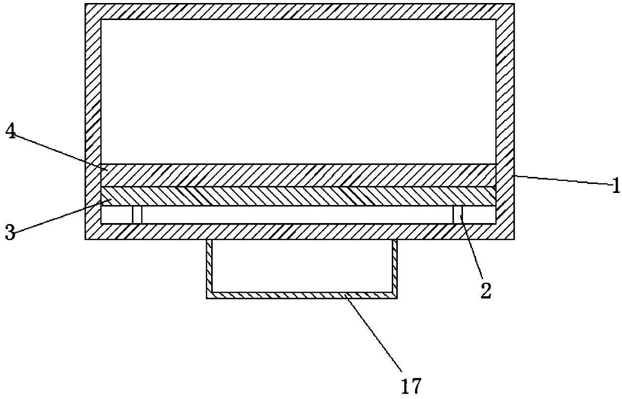
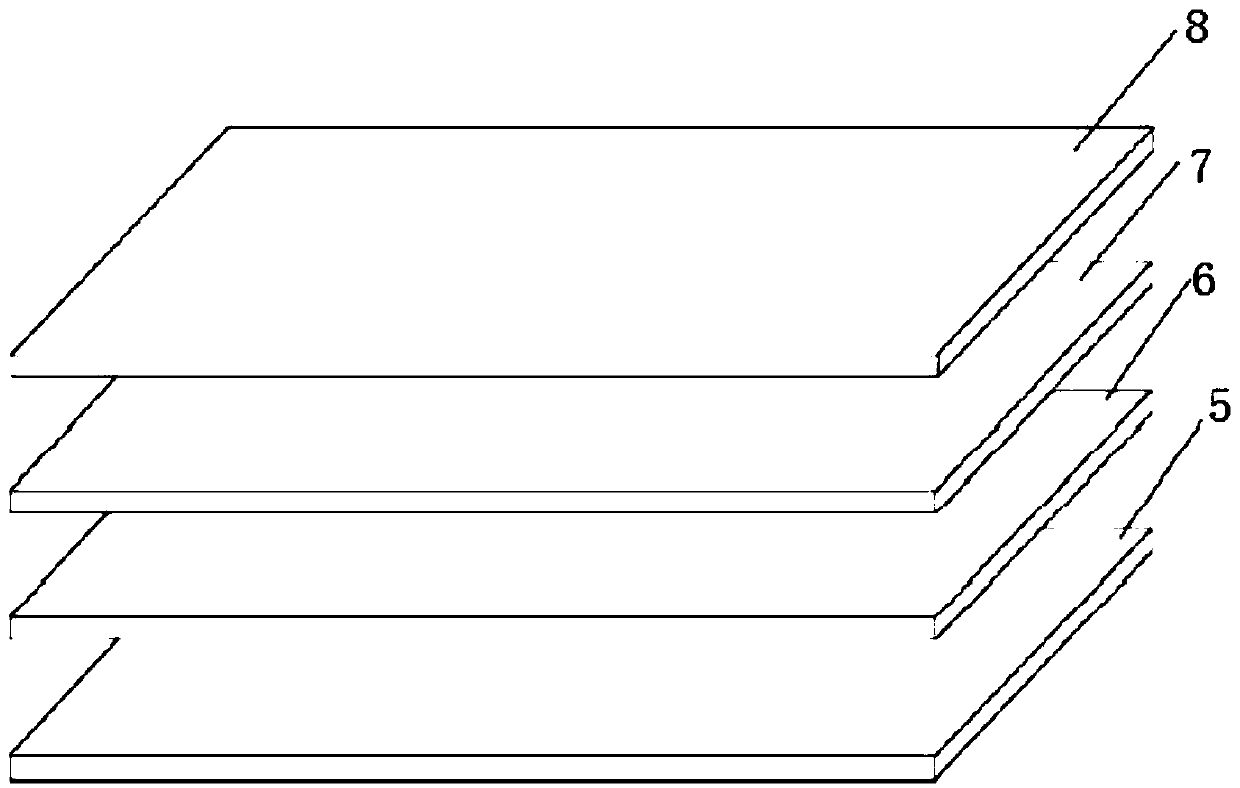
[0033] Such as figure 1 , 2 , an intelligent crib, comprising a bed frame 1, four telescopic connecting rods 2 are arranged symmetrically at the bottom of the bed frame 1, the upper ends of the telescopic connecting rods 2 are fixedly connected with a bed board 3, and an intelligent mattress 4 is placed on the bed board 3, the smart bed A ground cushion layer 5, a pressure monitoring layer 6, a temperature and humidity monitoring layer 7 and a top surface layer 8 are successively installed on the pad 4 from bottom to top. The pressure monitoring layer 6 is provided with a pressure sensor to monitor pressure changes, and the temperature and humidity monitoring layer 7 is provided with a temperature sensor and The humidity sensor monitors temperature and humidity changes, and a control board and an alarm device are arranged on one side of the bed frame 1. The control board is electrically connected to the pressure monitoring layer 6, the temperature and humidity monitoring layer...
Embodiment 2
[0040] Such as Figure 5 , different from Embodiment 1, the lower end of the bed frame 1 is provided with a base 16, and four lifting mechanisms are symmetrically arranged on the base 16, and the upper end of each lifting mechanism is connected with the bottom of the bed frame 1, and the lifting mechanism includes a worm shaft sleeve 9, a lifting mechanism The worm 10 and the lifting motor 11, the worm shaft sleeve 9 are fixedly connected to the upper end of the base 16, the lifting worm 10 is vertically penetrated on the worm shaft sleeve 9 and meshed with it, the lifting motor 11 is arranged on one side of the lower end of the lifting worm 10, and the lifting motor The output shaft of 11 is connected with lifting worm 10 transmissions by reduction gear, and lifting motor 11 connects control board, and the bottom of bedstead 1 is provided with plane bearing, and the upper end of lifting worm 10 is connected with plane bearing.
[0041] Four lifting mechanisms are arranged sym...
Embodiment 3
[0043] Such as Image 6 , 7 , 8. The difference from Embodiment 1 is that the two sides of the bed frame 1 are provided with locking structures 12 and railings 13 which are movably connected with the locking structures 12. , the locking structure 12 is located on both sides of the cross bar 14 , the side of the locking structure 12 away from the cross bar 14 is hinged to the bed frame 1 , and the locking structure 12 is provided with a groove body 15 suitable for the outer diameter of the cross bar 14 .
[0044] When the railing 13 needs to be opened, the locking structure 12 is rotated so that the groove body 15 of the locking structure 12 is facing the front side, and the cross bar 14 can be moved out at this moment, and the railing 13 is turned downward to fully open the railing 13; when the railing 13 needs to be closed , turn the railing 13 upwards until the crossbar 14 at the top of the railing 13 is in a horizontal position, rotate the locking structure 12, turn the gr...
PUM
 Abstract
Description
Claims
Application Information
 - R&D
- Intellectual Property
- Life Sciences
- Materials
- Tech Scout
- Unparalleled Data Quality
- Higher Quality Content
- 60% Fewer Hallucinations
Browse by: Latest US Patents, China's latest patents, Technical Efficacy Thesaurus, Application Domain, Technology Topic, Popular Technical Reports.
© 2025 PatSnap. All rights reserved.Legal|Privacy policy|Modern Slavery Act Transparency Statement|Sitemap|About US| Contact US: help@patsnap.com


