
Bionic finger and manipulator

A technology of manipulators and fingers, which is applied in the field of bionic fingers and manipulators, and can solve the problem of low flexion and extension flexibility of fingers

Pending Publication Date: 2019-12-24
JD DIGITS HAIYI INFORMATION TECHNOLOGY CO LTD
View PDF0 Cites 6 Cited by
  • Summary
  • Abstract
  • Description
  • Claims
  • Application Information

AI Technical Summary

Problems solved by technology

[0003] The purpose of the present invention is to provide a bionic finger to improve the problem of low flexion and extension flexibility of the fingers in the related art

Method used


Image

  • Bionic finger and manipulator
  • Bionic finger and manipulator
  • Bionic finger and manipulator

Examples


Embodiment Construction

[0033] The following will clearly and completely describe the technical solutions in the embodiments of the present invention with reference to the accompanying drawings in the embodiments of the present invention. Obviously, the described embodiments are only some, not all, embodiments of the present invention. The following description of at least one exemplary embodiment is merely illustrative in nature and in no way taken as limiting the invention, its application or uses. Based on the embodiments of the present invention, all other embodiments obtained by persons of ordinary skill in the art without creative efforts fall within the protection scope of the present invention.

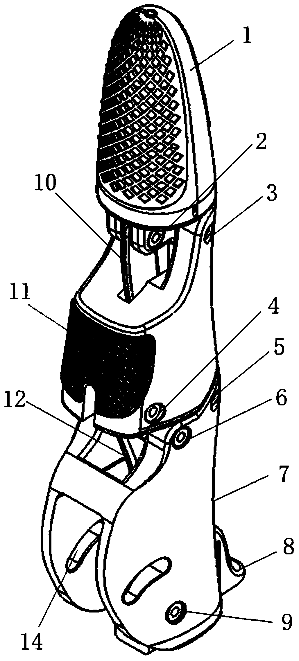
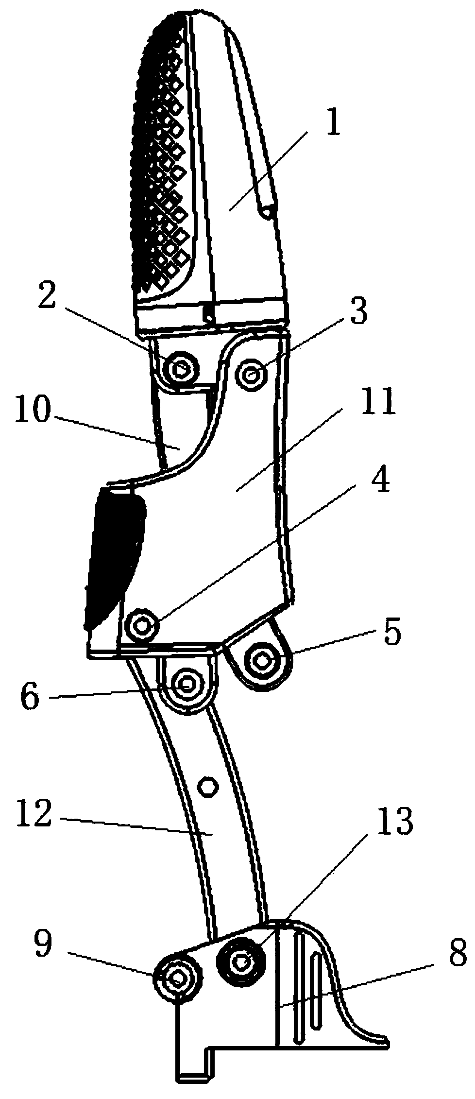
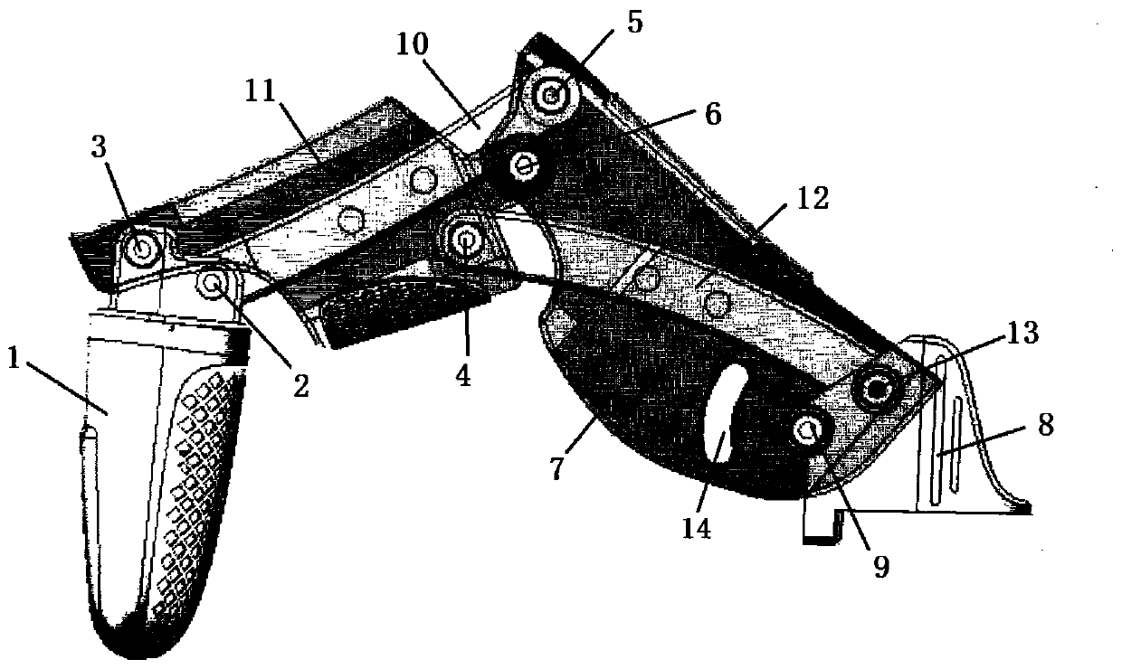
[0034] figure 1 A schematic structural view of the bionic finger of this embodiment is shown; figure 2 A schematic diagram showing the internal structure of the bionic finger of this embodiment; image 3 A perspective structural schematic diagram of the bionic finger of this embodiment is shown; ...


PUM


Abstract

The invention relates to a bionic finger and a manipulator. The bionic finger comprises a base (8), a first knuckle (7), a second knuckle (11), a third knuckle (1), a first connecting rod (12) and a second connecting rod (10), wherein the first knuckle (7) is rotatably connected with the base (8) through a first hinge part (9); the second knuckle ( 11) is rotatably connected with the first knuckle(7) through a second hinge part (6); the third knuckle (1) is rotatably connected with the second knuckle (11) through a third hinge part (3); one end of the first connecting rod (12) is rotatably connected with the base (8) through a fourth hinge part (13), and the other end of the first connecting rod (12) is rotatably connected with the second knuckle (11) through a fifth hinge part (4); and one end of the second connecting rod (10) is rotatably connected with the first knuckle (7) through a sixth hinge part (5), and the other end of the second connecting rod (10) is rotatably connected with the third knuckle (1) through a seventh hinge part (2). By applying the technical scheme, the problem of low flexibility of finger flexion and extension existing in the related art is solved.

Description

technical field [0001] The invention relates to the field of myoelectric bionic devices, in particular to a bionic finger and a manipulator. Background technique [0002] The existing myoelectric bionic finger mechanism uses a motor-driven link mechanism to achieve finger flexion and extension. The flexibility of finger flexion and extension is severely restricted by the size and number of links. The existence of a single-stage link mechanism greatly reduces the flexibility of finger flexion and extension. sex. Contents of the invention [0003] The present invention aims to provide a bionic finger to improve the problem of low flexibility in flexion and extension of the finger existing in the related art. [0004] According to an aspect of an embodiment of the present invention, a bionic finger is provided, and the bionic finger includes: [0005] base; [0006] the first knuckle is rotatably connected to the base through a first hinge; [0007] the second knuckle is ...

Claims


Application Information

Patent Timeline
Patent Type & Authority Applications(China)
IPC IPC(8): A61F2/58
CPCA61F2/586A61F2/58
Inventor 程二亭韩久琦蔡洁玉
Owner JD DIGITS HAIYI INFORMATION TECHNOLOGY CO LTD
Learn More