Semi-solid die-casting forming die

A die-casting, semi-solid technology, applied in the field of molds, can solve the problems of inconvenient operation, low output efficiency, large space occupation, etc., and achieve the effect of convenient assembly, high processing efficiency, and easy assembly

Inactive Publication Date: 2019-12-24
天津源特机械部件有限公司
View PDF14 Cites 0 Cited by
  • Summary
  • Abstract
  • Description
  • Claims
  • Application Information

AI Technical Summary

Problems solved by technology

[0002] Semi-solid die-casting refers to strong stirring during the solidification process of liquid metal, so that the dendrite network skeleton that is easy to form in ordinary casting is broken to form a dispersed granular structure, thereby making semi-solid metal liquid, and then Imported into the mold and die-cast into blanks or castings. For the current semi-solid die-casting molds, the current semi-solid die-casting molds basically include an upper mold and a lower mold, and the opposing surfaces between the upper mold and the lower mold. Mold cavity, in which the upper mold is a movable mold, and the lower mold is a fixed mold. The molds of this structure are all manually taken out of the product, and belong to the traditional old-fashioned structure, which occupies a large space, is inconvenient to operate, and has low discharge efficiency.

Method used


Image

  • Semi-solid die-casting forming die
  • Semi-solid die-casting forming die
  • Semi-solid die-casting forming die

Examples


Embodiment Construction

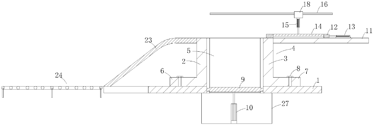
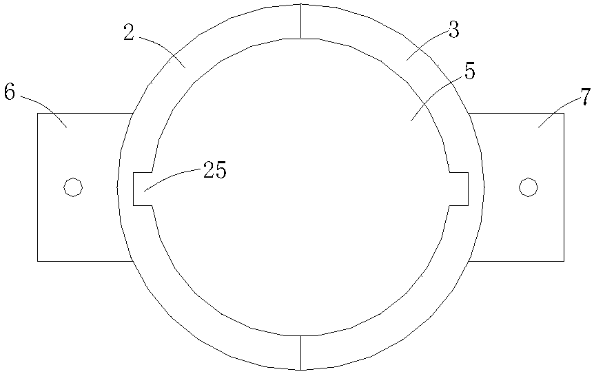
[0017] Such as Figure 1 to Figure 5 As shown, a semi-solid die-casting mold includes a base 1, a left mold cover 2 and a right mold cover 3 are arranged on the base 1, the cross sections of the left mold cover 2 and the right mold cover 3 are semicircular, and the left mold cover 2 Spliced ​​with the right mold cover 3 to form a cylindrical mold cover 4, the inside of the mold cover 4 is a mold cavity 5, the bottom of the left mold cover 2 is connected to the left fixed plate 6, the bottom of the right mold cover 3 is connected to the right fixed plate 7, and the left fixed plate The plate 6 and the right fixing plate 7 are fixed on the base 1 by bolts 8, the two ends of the cavity 5 are open, the base 1 is provided with an opening connected to the port of the cavity 5, and the opening is provided with a hole extending into the cavity 5. The lower die-casting plate 9 is provided with a first cylinder 10 connected to the lower die-casting plate 9 under the base 1;

[0018] Th...


PUM


Abstract

The invention relates to a semi-solid die-casting forming die which comprises a base; a left die sleeve and a right die sleeve are arranged on the base; the sections of the left die sleeve and the right die sleeve are semicircular; the left die sleeve and the right die sleeve are spliced to form a cylindrical die sleeve; a die cavity is formed in the die sleeve; the bottom of the left die sleeve is connected with a left fixed plate; the bottom of the right die sleeve is connected with a right fixed plate; the left fixed plate and the right fixed plate are fixed on the base through bolts; two ends of the die cavity are opened; an opening connected with an end opening of the die cavity is formed in the base; a lower die-casting plate extending into the die cavity is arranged at the opening;a first cylinder connected with the lower die-casting plate is arranged below the base; a horizontal supporting plate is arranged at the top of the die sleeve; a horizontal pushing plate is arranged on the supporting plate; one side of the horizontal pushing plate is connected with a second cylinder; the second cylinder is fixed on the supporting plate; and another opening is formed in the horizontal pushing plate, and an upper die-casting plate is arranged in the opening. The semi-solid die-casting forming die can automatically finish the die-casting and taking operation, and the processing efficiency is higher.

Description

technical field [0001] The invention relates to the field of molds, in particular to a semi-solid die-casting mold. Background technique [0002] Semi-solid die-casting refers to strong stirring during the solidification process of liquid metal, so that the dendrite network skeleton that is easy to form in ordinary casting is broken to form a dispersed granular structure, thereby making semi-solid metal liquid, and then Imported into the mold and die-cast into a blank or casting. For the current semi-solid die-casting mold, the current semi-solid die-casting mold basically includes an upper mold and a lower mold, and the opposing surface between the upper mold and the lower mold. The mold cavity, wherein the upper mold is a movable mold, and the lower mold is a fixed mold. The molds of this structure are all manually taken out of the product, and belong to the traditional old-fashioned structure, which occupies a large space, is inconvenient to operate, and has low discharge...

Claims


Application Information

Patent Timeline
Patent Type & Authority Applications(China)
IPC IPC(8): B22D17/22
CPCB22D17/007B22D17/22
Inventor 吕荣昌
Owner 天津源特机械部件有限公司
Why Eureka
Try Eureka