Lower vehicle-body structure

A car body and structure technology, which is applied in the direction of superstructure, superstructure sub-assembly, and connection between superstructure sub-assemblies, can solve the problem that the rigidity of the car body is not enough to suppress the decline, and achieve a firm fixed structure, The effect of improving the rigidity of the vehicle body

Active Publication Date: 2019-12-24
MAZDA MOTOR CORP
View PDF10 Cites 0 Cited by
  • Summary
  • Abstract
  • Description
  • Claims
  • Application Information

AI Technical Summary

Problems solved by technology

[0007] In the vehicle body structure of Patent Document 1, the mounting member is fixed to the underside of the floor tunnel, but in such a structure, it is not enough to suppress the decrease in the rigidity of the vehicle body, and there is still room for improvement.

Method used


Image

  • Lower vehicle-body structure
  • Lower vehicle-body structure
  • Lower vehicle-body structure

Examples


Embodiment Construction

[0040] A lower vehicle body structure according to an embodiment of the present invention will be described below with reference to the drawings.

[0041] [overall composition]

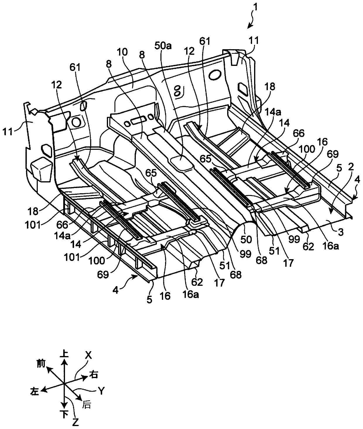
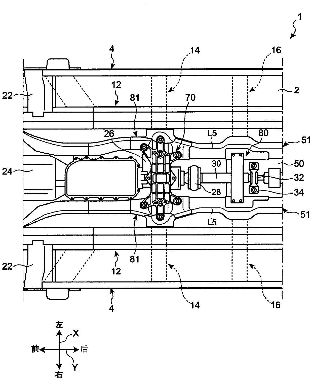
[0042] figure 1 It is a perspective view showing the lower vehicle body structure of this embodiment. figure 2 It is a plan view showing the structure of the lower vehicle body. image 3 It is a bottom view showing the structure of the lower body. In the following description, the vehicle width direction, the vehicle front-rear direction, and the vehicle vertical direction of the automobile 1 provided with the lower body structure of the present embodiment may be referred to as X direction, Y direction, and Z direction, respectively.

[0043] refer to figure 1 The automobile 1 provided with the lower body structure of this embodiment includes: a vehicle body floor 2 constituting the floor of the interior space of the vehicle compartment; a pair of sides extending in the Y direction along both sid...


PUM


Abstract

A lower vehicle-body structure is provided which can properly improve the vehicle-body rigidity. The lower vehicle-body structure comprises a vehicle floor (2) comprising a bottom face portion (3) anda floor tunnel (50) which protrudes upwardly and extends in a vehicle longitudinal direction; floor cross members (14) extending in a vehicle width direction; and a connecting member (70) provided tooverlap the floor cross members (14) in the vehicle longitudinal direction and to extend in the vehicle width direction and fixed to at least one of the vehicle floor (2) and the floor cross members(14) at plural fixation positions P1, P2, P3, P4. These plural fixation positions P1, P2, P3, P4 are located at plural different levels in a range of a height of the floor cross members (14).

Description

technical field [0001] The present invention relates to underbody construction. Background technique [0002] In vehicles such as FR (Front Rear Drive) and 4WD (Four Wheel Drive) vehicles, a propeller shaft extending in the vehicle front-rear direction may be provided in a power transmission path from a drive source to drive wheels. The propeller shaft is usually arranged in a floor tunnel provided at the center of the vehicle body floor in the vehicle width direction. In addition, for example, in a vehicle equipped with a so-called longitudinally mounted powertrain, at least a part of the transmission may be disposed in the floor tunnel. [0003] In addition, in order to increase the rigidity of the vehicle body, etc., a floor cross member extending in the vehicle width direction may be provided on the upper surface of the vehicle body floor. In the vehicle body having the above-mentioned floor tunnel, the floor cross member is divided into left and right through the floo...

Claims


Application Information

Patent Timeline
Patent Type & Authority Applications(China)
IPC IPC(8): B62D25/20
CPCB62D25/20B60N2/015B62D25/025B62D25/2018B62D25/2036B62D27/02B62D25/2009
Inventor 枣裕贵影山和宏数面宏昭桑野祐希岩田强志戎本圭佑松冈秀典
Owner MAZDA MOTOR CORP
Why Eureka
Try Eureka