Rope releasing device of unmanned aerial vehicle

The technology of a machine rope releaser and a rope reel is applied in the field of fire rescue equipment, which can solve the problems of the unmanned aerial vehicle rope releaser being difficult to pull the rope to the ground, and achieve the effect of safety in use.

Active Publication Date: 2019-12-24
ZHEJIANG TOPSUN LOGISTIC CONTROL CO LTD
View PDF6 Cites 2 Cited by
  • Summary
  • Abstract
  • Description
  • Claims
  • Application Information

AI Technical Summary

Problems solved by technology

[0004] The purpose of the present invention is to solve the above-mentioned problems in the existing technology, and propose a UAV rope release device, which solves the problem that the existing UAV rope release device is difficult to perform traction rope landing operation at high altitude

Method used


Image

  • Rope releasing device of unmanned aerial vehicle
  • Rope releasing device of unmanned aerial vehicle
  • Rope releasing device of unmanned aerial vehicle

Examples


Embodiment 1

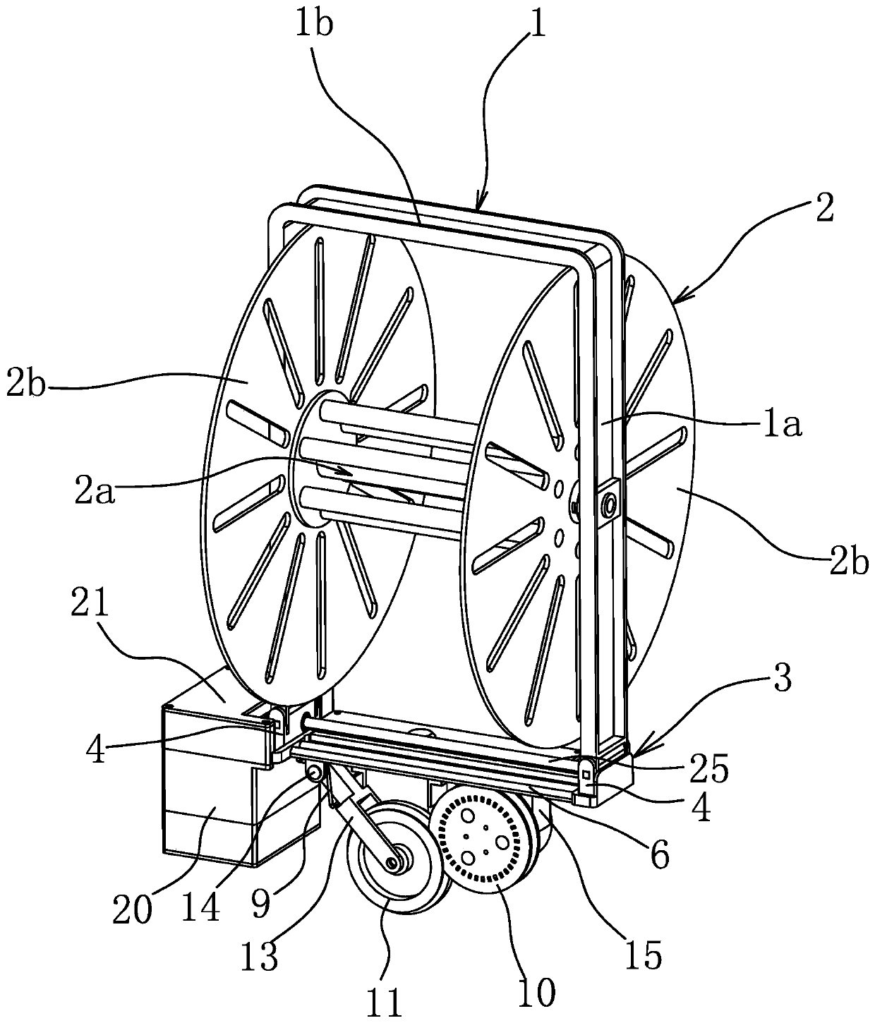
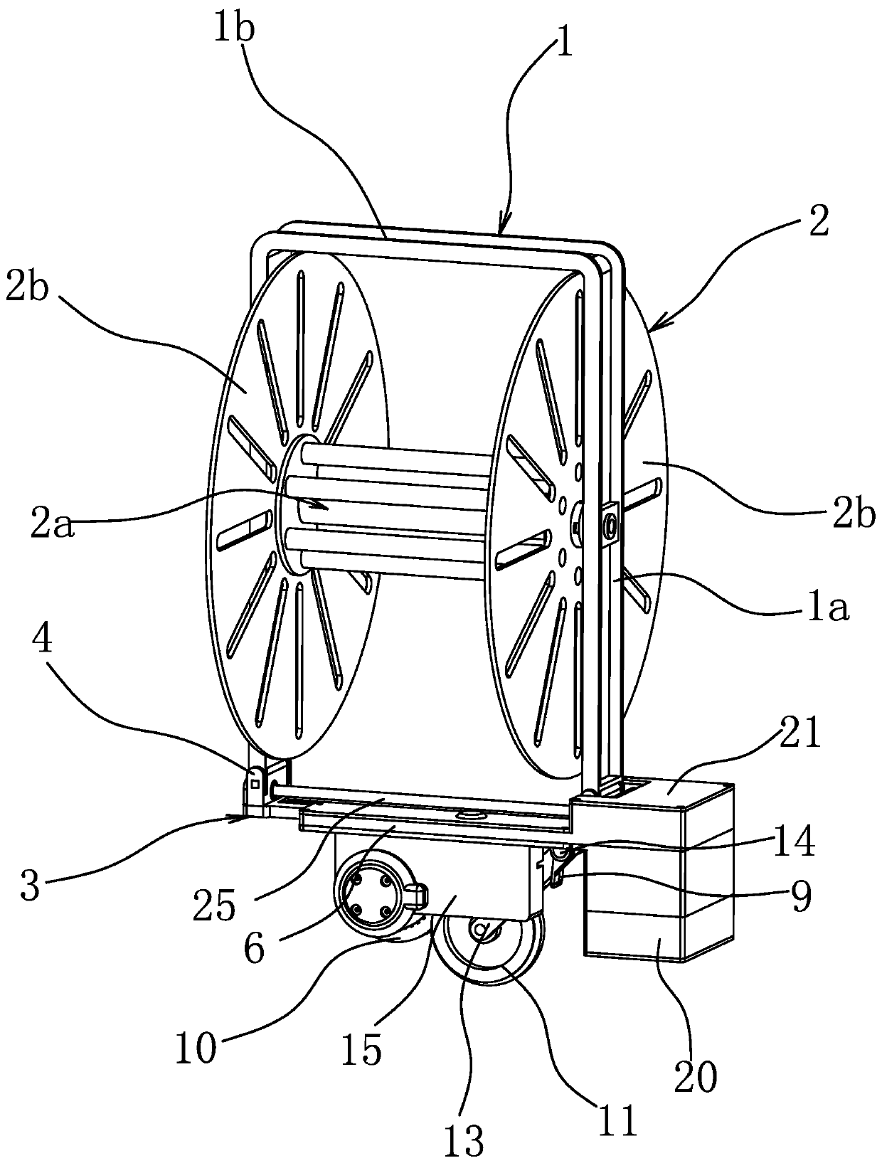
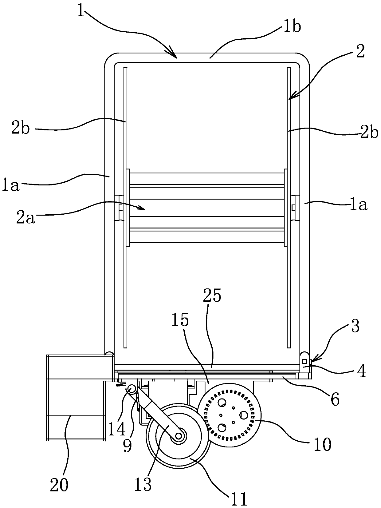
[0045] Such as figure 1 , figure 2 with image 3 As shown, the UAV rope release device includes a rope reel support 1, a throwing frame 3 and a rope reel 2 for winding the traction rope. The rope reel 2 includes a reel 2a, and the two ends of the reel 2a are respectively connected with a 2a is perpendicular to the rope retaining plate 2b. The throwing frame 3 is connected to the bottom of the rope reel support 1 through connecting parts. The rope reel support 1 is U-shaped and includes a top beam 1b and two opposite side support beams 1a, and the rope reel 2 is rotatably connected to the two side support beams. Between 1a, the top beam 1b is used to connect with the UAV, and the throwing frame 3 is also provided with a rope release mechanism for connecting with the traction rope and controlling the speed of the traction rope.

[0046] Specifically, such as image 3 with Figure 4As shown, the bottom surface of the throwing frame 3 is fixedly connected with a motor cover ...

Embodiment 2

[0059] The structure and principle of this embodiment are basically the same as that of Embodiment 1, the difference is that, as Figure 17 As shown, the connecting parts include a grasping manipulator 26 arranged at the bottom of the rope reel support 1, and the throwing frame 3 has a grasping part 31 clamped by the grasping manipulator 26, and the driving member 7 can control 26 grabbing manipulators. open or closed.

Embodiment 3

[0061] The structure and principle of this embodiment are basically the same as that of Embodiment 1, the difference is that, as Figure 18 As shown, the throwing frame 3 is connected to the side of the rope reel support 1 through a connecting part. Specifically, the two side support beams 1a of the rope reel support 1 are respectively connected to an extension frame 1c, and a locking hole is provided on the extension frame 1c. 1a2, the connecting part includes a locking piece 5 arranged on the throwing frame 3, the locking piece 5 extends into the locking hole 1a2, when the driving piece 7 drives the gear to rotate, it drives the locking piece 5 to move, so that the locking piece 5 escapes from the locking hole 1a2 , and then realize that the throwing frame 3 breaks away from the rope reel support 1 .


PUM


Abstract

The invention provides a rope releasing device of an unmanned aerial vehicle, belongs to the technical field of fire rescue equipment, and solves the problem that it is difficult for existing rope releasing devices of unmanned aerial vehicles to perform the traction rope landing operation at the high altitude. The rope releasing device of the unmanned aerial vehicle comprises a rope reel support and a rope reel for winding a traction rope; the top of the rope reel support is connected with the unmanned aerial vehicle; the rope releasing device of the unmanned aerial vehicle further comprises athrowing frame and a driving piece; the throwing frame is connected to the side or the bottom of the rope reel support through a connecting component; and the driving piece can drive the connecting component to act to enable the throwing frame to be separated from the rope reel support. According to the rope releasing device of the unmanned aerial vehicle, when the traction rope is realized to belanded, all that is required is to control the action of the driving piece remotely and throw the throwing frame, the operation is very convenient, and the traction rope can be arranged efficiently during high-rise fire-fighting.

Description

technical field [0001] The invention belongs to the technical field of firefighting and rescue equipment, and relates to a rope releaser for an unmanned aerial vehicle. Background technique [0002] In recent years, with the acceleration of urbanization across the country, rows of high-rise buildings have become one of the symbols of urban modernization. Due to their large size and dense population, high-rise buildings have many sources of danger and large fire loads. It has brought severe challenges. At present, it is difficult to extinguish a fire in a high-rise building quickly, and it has always been a difficult problem for people to overcome. On the one hand, although the invention of the aerial ladder can send the fire water gun to a high place for fire extinguishing, the use of the aerial ladder is limited by the space, and it is difficult to use the aerial ladder to extinguish the fire in some communities where the road is not wide; The usual height of the existing ...

Claims


Application Information

Patent Timeline
Patent Type & Authority Applications(China)
IPC IPC(8): B64D1/02
CPCB64D1/02
Inventor 阮卜琴牛胜良
Owner ZHEJIANG TOPSUN LOGISTIC CONTROL CO LTD
Why Eureka
Try Eureka