Motor rotor, motor and compressor

A motor rotor and rotor core technology, which is applied in the fields of compressors, motor rotors, and motors, can solve the problems of high manufacturing cost, low utilization rate, and high permanent magnet consumption of rotors and even motors, so as to improve utilization rate, reduce consumption, and reduce The effect of manufacturing costs

Active Publication Date: 2019-12-24
ZHUHAI GREE REFRIGERATION TECH CENT OF ENERGY SAVING & ENVIRONMENTAL PROTECTION
View PDF7 Cites 2 Cited by
  • Summary
  • Abstract
  • Description
  • Claims
  • Application Information

AI Technical Summary

Problems solved by technology

[0003] The permanent magnet layout of the tangential flux permanent magnet motor in the prior art is as follows: figure 1 As shown, in order to provide a larger motor output torque in this structure, the amount of permanent magnets is relatively high (especially the width is widened), and the utilization rate is low, resulting in high manufacturing costs for the rotor and even the motor.

Method used


Image

  • Motor rotor, motor and compressor
  • Motor rotor, motor and compressor
  • Motor rotor, motor and compressor

Examples


Embodiment Construction

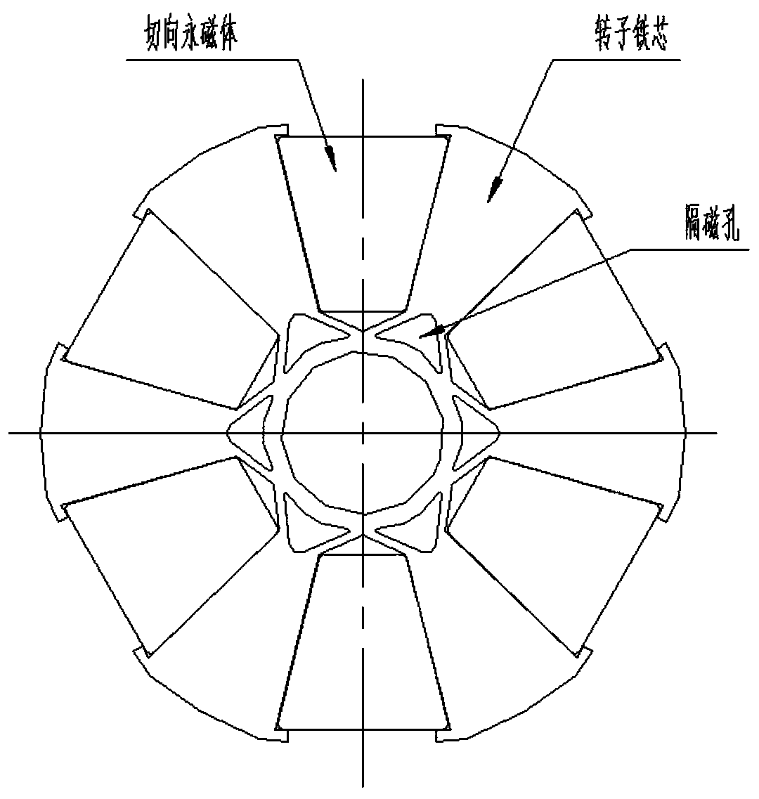
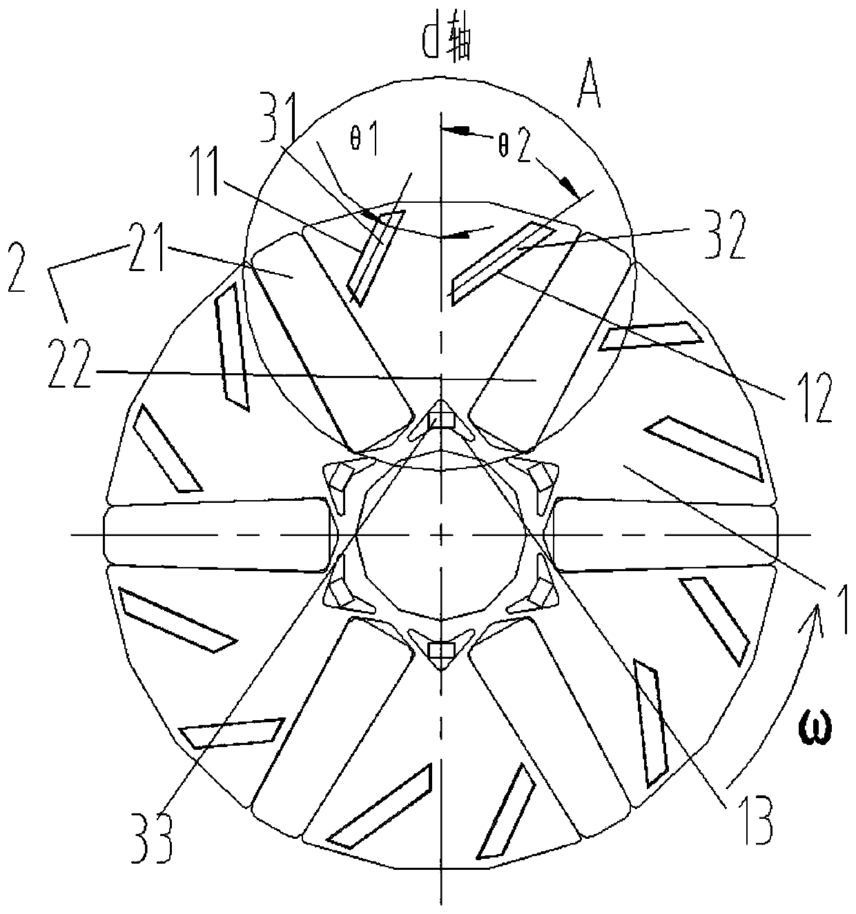
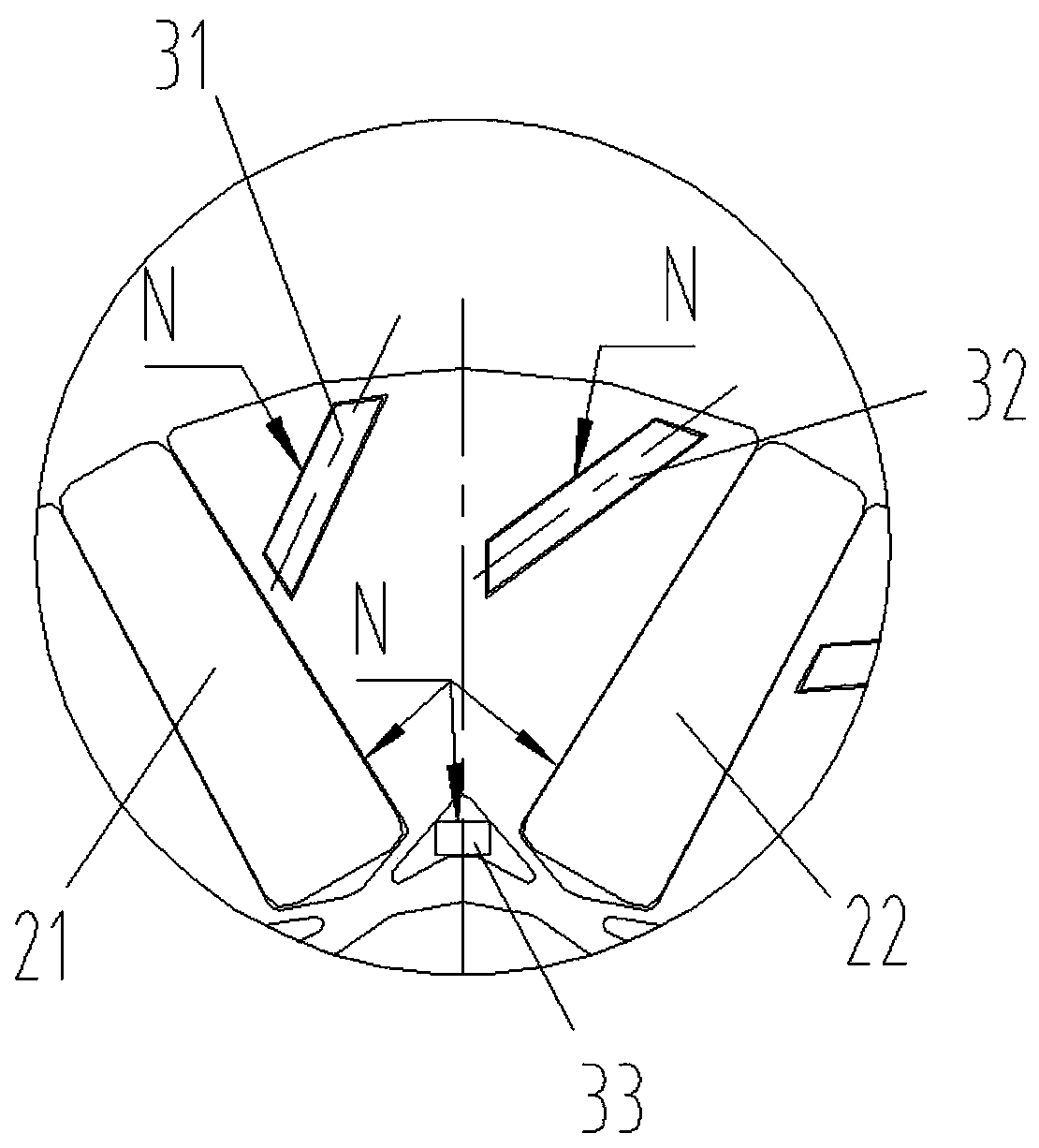
[0025] see in conjunction Figure 2 to Figure 5 As shown, according to an embodiment of the present invention, a motor rotor is provided, including a rotor core 1, M tangential permanent magnets 2 arranged at intervals along the circumference of the rotor core 1, and the tangential permanent magnets 2 are arranged along the The radial direction of the rotor core 1 extends, and the rotor core 1 between any two adjacent tangential permanent magnets 2 is configured with a first magnetic isolation slot 11, which is perpendicular to the rotor core. On any section of the axis of 1, the extension direction of the first magnetic isolation slot 11 forms an angle θ1 with the d-axis, 0°<θ1<90°, any two adjacent tangential permanent magnets 2 The opposite side has the same polarity, and the first magnetic isolation slot 11 has a first end close to the axis of the rotor core 1 and a second end far away from the axis of the rotor core 1, along the In the direction of rotation of the rotor ...


PUM


Abstract

The invention provides a motor rotor, a motor and a compressor. The motor rotor comprises a rotor core and M tangential permanent magnets arranged at intervals along a circumferential direction of therotor core, the tangential permanent magnets extend along a radial direction of the rotor core, and a first magnetic isolation groove is formed in the rotor core between any two adjacent tangential permanent magnets. On any section perpendicular to an axis of the rotor core, an included angle theta 1 which is larger than 0 degree and smaller than 90 degrees is formed between an extending direction of the first magnetic isolation groove and a d axis, the polarities of facing sides of any two adjacent tangential permanent magnets are the same, each first magnetic isolation groove is provided with a first end close to the axis of the rotor core and a second end away from the axis of the rotor core, and the first end is located in front of the second end in the rotating direction of the rotoriron core. The reluctance torque can be fully utilized to improve the output torque of the motor, the use amount of the permanent magnets is reduced, the utilization rate of the permanent magnets isimproved, and the manufacturing cost of the rotor and even the motor is reduced.

Description

technical field [0001] The invention belongs to the technical field of motor manufacturing, and in particular relates to a motor rotor, a motor and a compressor. Background technique [0002] The embedded permanent magnet motor is divided into two structures: radial flux and tangential flux according to the direction of flux. For permanent magnet motors with tangential flux structure, the permanent magnets in the rotor extend along the radial direction of the rotor, which can produce a "magnetism gathering effect". Therefore, compared with the radial flux structure, the flux utilization rate is higher, and the motor has It has the advantages of small size, light weight, large torque, high power density, high motor efficiency and good dynamic performance. [0003] The permanent magnet layout of the tangential flux permanent magnet motor in the prior art is as follows: figure 1 As shown, in order to provide a larger motor output torque in this structure, the amount of perman...

Claims


Application Information

Patent Timeline
Patent Type & Authority Applications(China)
IPC IPC(8): H02K1/27
CPCH02K1/2773H02K2213/03
Inventor 张凯陈华杰高明世马梓净刘通
Owner ZHUHAI GREE REFRIGERATION TECH CENT OF ENERGY SAVING & ENVIRONMENTAL PROTECTION
Why Eureka
Try Eureka