Synchronous reluctance permanent magnet motor rotor structure

A permanent magnet motor and rotor structure technology, which is applied in the direction of magnetic circuit shape/style/structure, magnetic circuit rotating parts, magnetic circuit, etc., can solve problems such as poor starting performance, low motor power density, and large motor volume. Achieve volume reduction, good start-up performance, and high power density

Pending Publication Date: 2020-04-07
淮安精英电气科技有限公司
View PDF0 Cites 0 Cited by
  • Summary
  • Abstract
  • Description
  • Claims
  • Application Information

AI Technical Summary

Problems solved by technology

[0002] The permanent magnet synchronous motor is equipped with permanent magnets on the rotor, and its structure is evenly distributed on the outside of the rotor. The rotor of the synchronous reluctance motor is distributed with closed slots, and there is no need to install permanent magnets, resulting in a lower power density of the motor and a smaller volume of the motor. Large, poor starting performance, for this reason, we propose a synchronous reluctance permanent magnet motor rotor structure

Method used


Image

  • Synchronous reluctance permanent magnet motor rotor structure

Examples


Embodiment Construction

[0011] In order to make the technical means, creative features, goals and effects achieved by the present invention easy to understand, the present invention will be further described below in conjunction with specific embodiments.

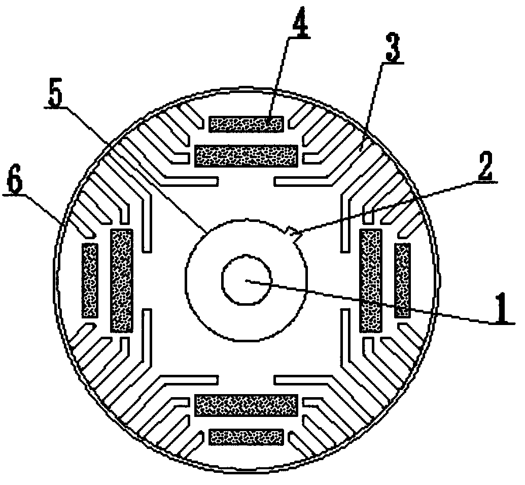
[0012] like figure 1 As shown, a synchronous reluctance permanent magnet motor rotor structure includes a permanent magnet 1, a salient pole 2, a punching plate closed slot 3, a magnetic steel slot 4, a rotor 5 and a housing 6, and the inner side of the housing 6 is provided with a punching The sheet closed slots 3, the magnetic steel slots 4 are arranged between the punched sheet closed slots 3, the housing 6 is provided with a rotor 5 and the rotor 5 is provided with a permanent magnet 1.

[0013] Wherein, a salient pole 2 is provided outside the rotor 5 and the salient pole 2 is located in the axial direction of the rotor 5 .

[0014] In this example, if figure 1 As shown, the salient pole 2 can better increase the difference between the d-ax...


PUM


Abstract

The invention discloses a synchronous reluctance permanent magnet motor rotor structure. The structure comprises a permanent magnet, a salient pole, punching sheet closed grooves, magnetic steel grooves, a rotor and a shell, the punching sheet closed grooves are formed in the inner side of the shell, the magnetic steel grooves are formed between the punching sheet closed grooves, the rotor is arranged in the shell, and the permanent magnet is arranged in the rotor. According to the invention, the permanent magnet is placed in the rotor, and the salient pole is added in the axial direction of the rotor to better increase the difference between the d-axis inductance and the q-axis inductance, so that the reluctance torque of the motor is more effectively improved, the power density of the motor is higher, the size of the motor is reduced, the starting performance of the motor is better, and the motor is suitable for wide popularization and application.

Description

technical field [0001] The invention relates to the technical field of motor structure, in particular to a synchronous reluctance permanent magnet motor rotor structure. Background technique [0002] The permanent magnet synchronous motor is equipped with permanent magnets on the rotor, and its structure is evenly distributed on the outside of the rotor. The rotor of the synchronous reluctance motor is distributed with closed slots, and there is no need to install permanent magnets, resulting in a lower power density of the motor and a smaller volume of the motor. Large, poor starting performance, for this reason, we propose a synchronous reluctance permanent magnet motor rotor structure. Contents of the invention [0003] The main purpose of the present invention is to provide a synchronous reluctance permanent magnet motor rotor structure, by putting permanent magnets into the rotor, a salient pole is added in the axial direction of the rotor, and its function is to bett...

Claims


Application Information

Patent Timeline
Patent Type & Authority Applications(China)
IPC IPC(8): H02K1/27
CPCH02K1/276
Inventor 卢英辉曹胜
Owner 淮安精英电气科技有限公司
Why Eureka
Try Eureka