Rotor punching sheet structure of permanent magnet synchronous motor for electric motorcycle and rotor thereof

A permanent magnet synchronous motor, rotor punching technology, applied in synchronous machine parts, electric components, magnetic circuits, etc., can solve the problems of poor sinusoidal back electromotive force, large leakage flux of the motor, and small high-efficiency operating area. The effect of increasing motor output torque, increasing motor reluctance torque, and improving field weakening speed expansion capability

Pending Publication Date: 2022-04-15
擎风电驱动科技(常州)有限公司
View PDF5 Cites 0 Cited by
  • Summary
  • Abstract
  • Description
  • Claims
  • Application Information

AI Technical Summary

Problems solved by technology

[0003] However, in the design and practical application of most permanent magnet synchronous motor rotors for electric motorcycles, there are many problems that we cannot ignore, such as large motor leakage flux, low power factor, poor sinusoidality of back electromotive force, low efficiency, vibration and noise Large, high-efficiency operating area is small

Method used


Image

  • Rotor punching sheet structure of permanent magnet synchronous motor for electric motorcycle and rotor thereof
  • Rotor punching sheet structure of permanent magnet synchronous motor for electric motorcycle and rotor thereof
  • Rotor punching sheet structure of permanent magnet synchronous motor for electric motorcycle and rotor thereof

Examples


Embodiment 1

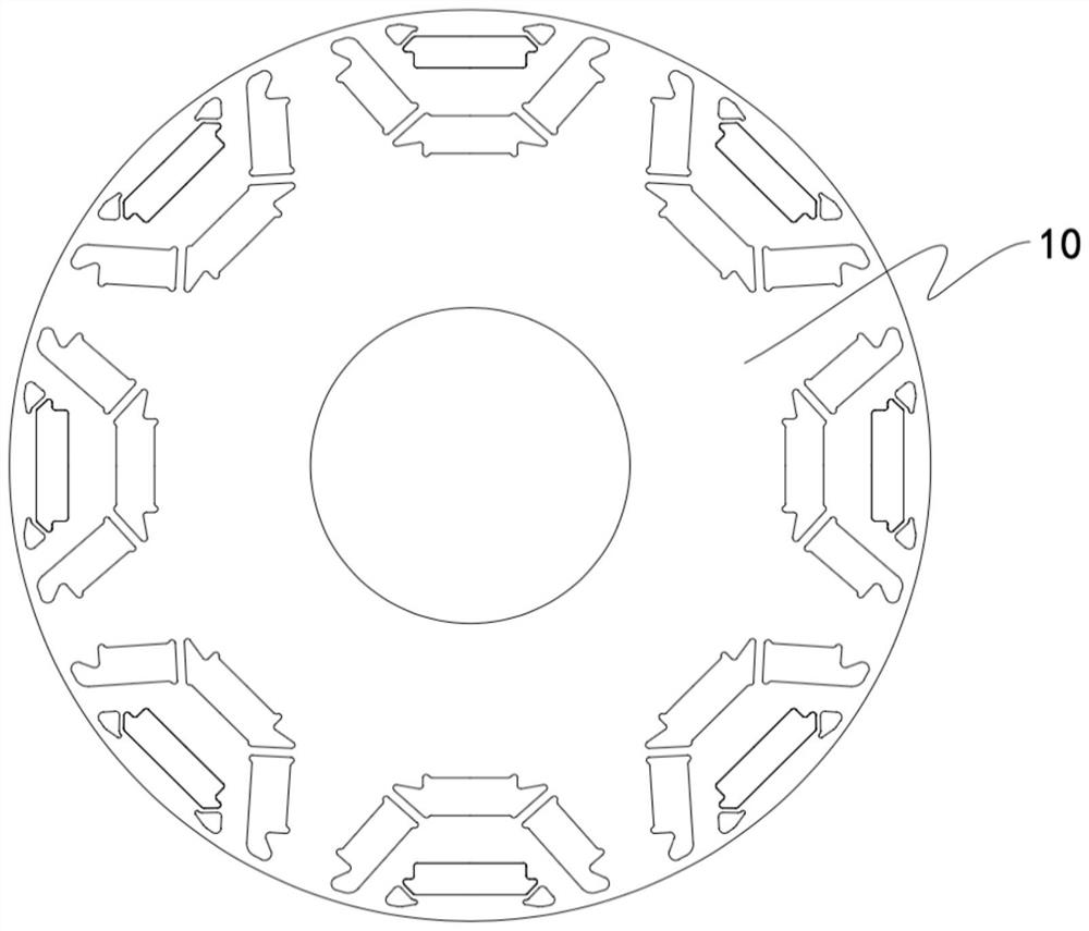
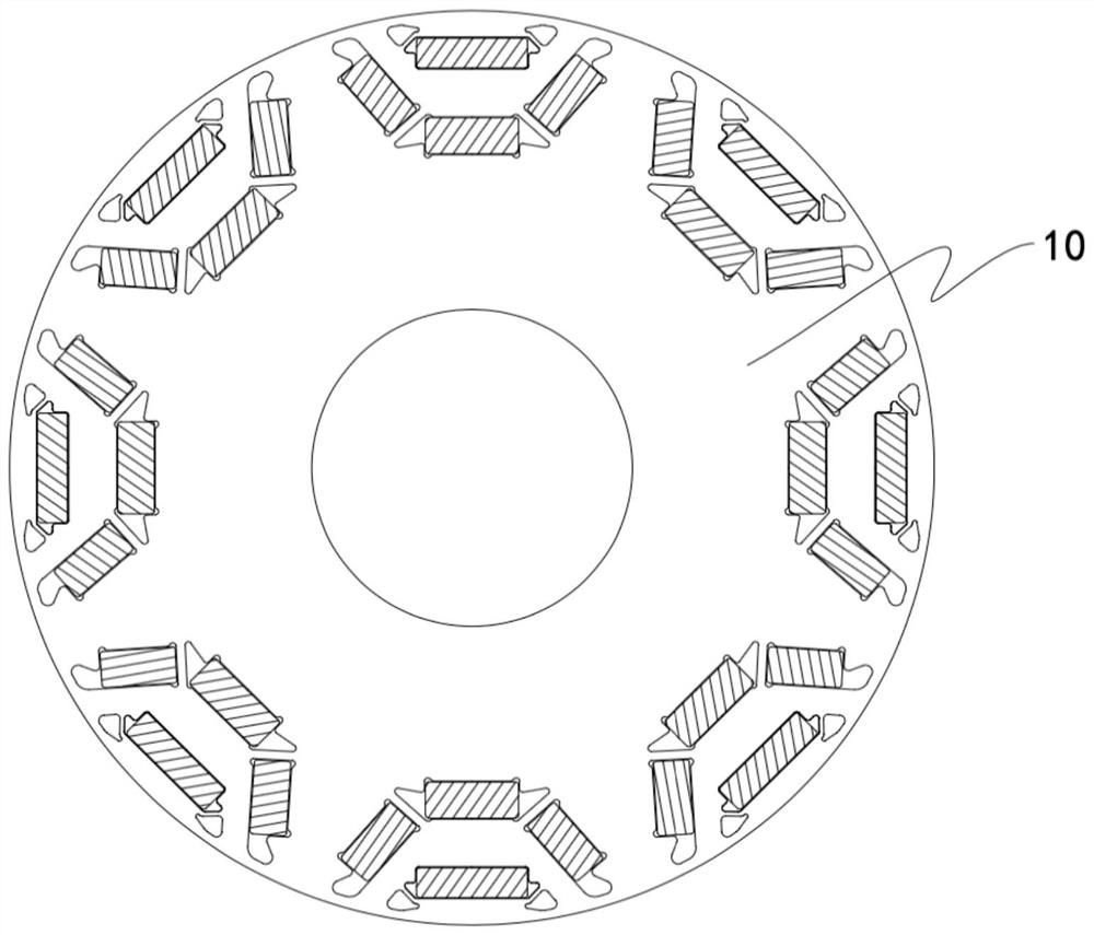
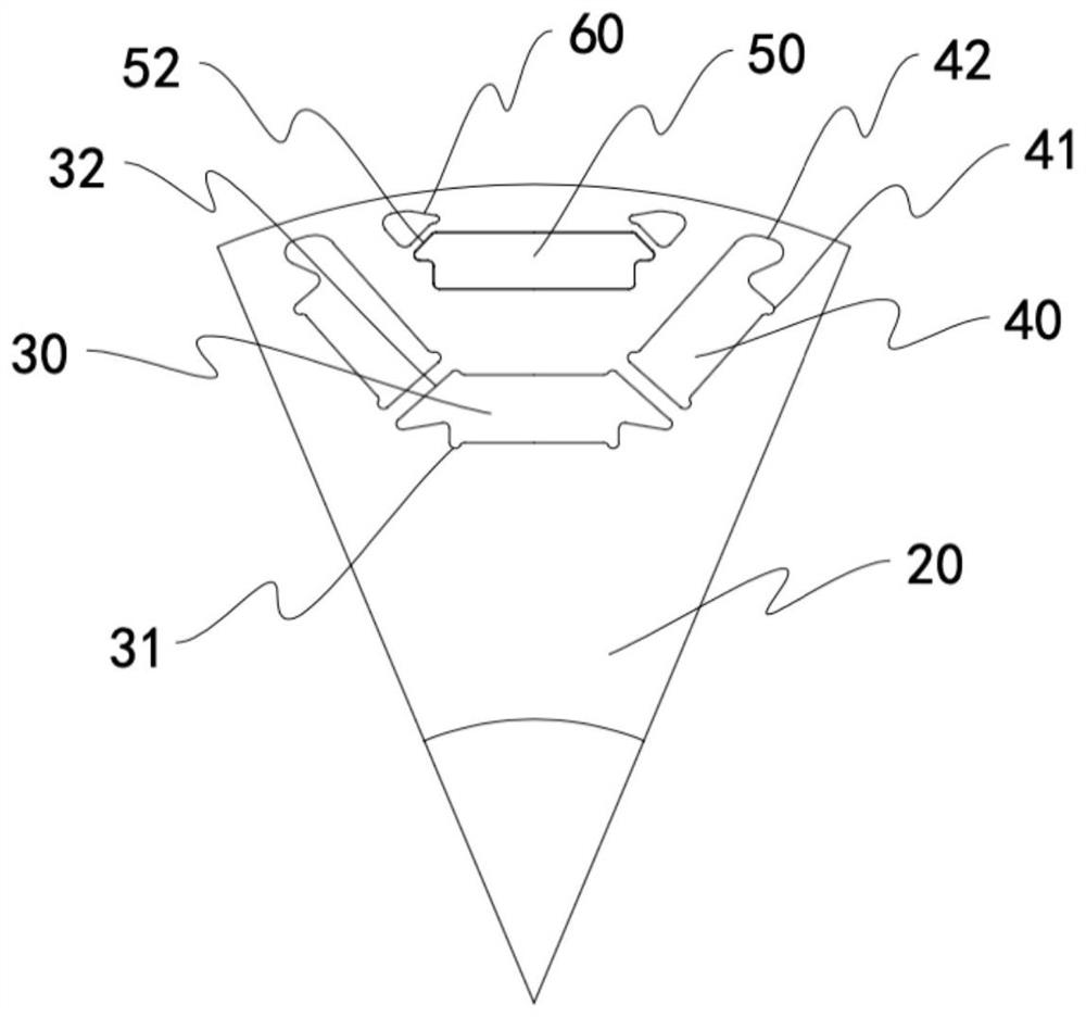
[0026] Such as Figure 1-4 As shown, a permanent magnet synchronous motor rotor punching structure for electric motorcycles includes a punching body 10, and the punching body 10 is divided into a plurality of sectoral areas 20 of equal shape and size, and the sectoral areas 20 are close to the arc edge. A groove group is provided, and the groove group includes an inner layer groove body and an outer layer groove body respectively for installing the magnetic steel 70, and the outer layer groove body is arranged on the side of the inner layer groove body close to the arc edge of the fan-shaped area 20; The inner layer tank body includes an inner layer middle groove 30 and an inner layer side groove 40 arranged on both sides of the inner layer middle groove 30, the inner layer middle groove 30 and the inner layer side groove 40 are all rectangular, the The inner layer middle groove 30 is arranged symmetrically at the center line of the fan-shaped area 20, and the two inner layer ...

Embodiment 2

[0038] This embodiment is basically the same as Embodiment 1, the difference is that the structure of the outer tank body is different, such as Figure 5 As shown, the outer layer tank body in this embodiment includes an outer layer middle groove 50 and outer middle magnetic isolation grooves 52 arranged on both sides of the outer layer middle groove 50, and the outer layer middle groove 50 is rectangular and symmetrical Located at the center line of the fan-shaped area 20, the two corners of the side of the outer layer middle groove 50 near the center of the fan-shaped area 20 are respectively provided with outwardly protruding outer layer middle part convex grooves 51, and the outer layer middle part is convex. The protruding direction of the slot 51 is consistent with the direction of both sides of the outer middle slot 50, and the outer middle magnetic isolation slot 52 is arranged at two corners of the outer middle slot 50 near the arc edge of the fan-shaped area 20, so T...

Embodiment 3

[0041] This embodiment is basically the same as Embodiment 1, the difference is that the structure of the outer tank body is different, such as Figure 6 As shown, the outer tank body in this embodiment includes two outer layer side tanks 60 arranged in a "V" shape and arranged symmetrically with respect to the center line of the fan-shaped area 20. The "V"-shaped opening faces the fan-shaped area 20 arc edge, the outer layer side groove 60 is rectangular, and the two corners of the side edge of the outer layer side groove 60 close to the center line of the fan-shaped area 20 are respectively provided with outwardly protruding outer layer side protrusions. Groove 61, the side of the outer layer side groove 60 away from the center line of the fan-shaped area 20 is provided with an outer layer side convex groove 61 at one end close to the center line of the fan-shaped area 20, the convex groove 61 of the outer layer side convex groove 61 The starting direction is consistent with...


PUM


Abstract

The invention discloses a permanent magnet synchronous motor rotor punching sheet structure for an electric motorcycle, which comprises a punching sheet body, the punching sheet body is divided into a plurality of fan-shaped areas with the same shape and size, groove groups are arranged in the fan-shaped areas close to arc edges, and each groove group comprises an inner-layer groove body and an outer-layer groove body which are respectively used for installing magnetic steel. The outer groove body is arranged on one side, close to the arc edge of the fan-shaped area, of the inner groove body; the inner-layer groove body comprises an inner-layer middle groove and inner-layer side grooves formed in the two sides of the inner-layer middle groove, the inner-layer middle groove and the inner-layer side grooves are rectangular, the inner-layer middle groove is symmetrically formed in the center line of the fan-shaped area, and the two inner-layer side grooves are symmetrically formed in the two sides of the inner-layer middle groove with the center line of the fan-shaped area as the center; inner-layer middle magnetic isolation grooves are formed in the two side edges of the inner-layer middle groove correspondingly, and inner-layer side magnetic isolation grooves are formed in the side edges, away from the inner-layer middle groove, of the inner-layer side grooves; and the outer-layer groove bodies are symmetrically arranged at the center lines of the fan-shaped areas. The invention further discloses the permanent magnet synchronous motor rotor for the electric motorcycle.

Description

technical field [0001] The invention relates to the technical field of motor equipment, in particular to a punching structure of a rotor of a permanent magnet synchronous motor for an electric motorcycle and the rotor thereof. Background technique [0002] With the continuous deterioration of the natural environment and the tight supply of fossil energy, electric vehicles are an effective path to ensure the flexibility of human mobility and realize the sustainable development of the automobile industry while reducing dependence on fossil fuels and environmental pollution. As a new type of clean energy, electric energy will become an inevitable trend of future energy development, and electric vehicles will inevitably replace traditional fuel vehicles and become the dominant means of transportation in the new era. Electric vehicles include electric passenger cars, electric buses, electric logistics vehicles, electric motorcycles and electric bicycles, etc., which use power as ...

Claims


Application Information

Patent Timeline
Patent Type & Authority Applications(China)
IPC IPC(8): H02K1/276H02K21/02
Inventor 李玲徐飞李圣悦
Owner 擎风电驱动科技(常州)有限公司
Why Eureka
Try Eureka