
Multi-shaft multi-direction tilting type multi-rotor aircraft transmission system

A multi-rotor aircraft and transmission system technology, applied in the field of multi-axis multi-directional tilt multi-rotor aircraft transmission system, can solve the problems of high energy consumption, large take-off weight, low stability and safety, etc., and achieve high flight efficiency , Wide adaptability and cleverly designed effects

Pending Publication Date: 2019-12-27
吴华锋
View PDF0 Cites 4 Cited by
  • Summary
  • Abstract
  • Description
  • Claims
  • Application Information

AI Technical Summary

Problems solved by technology

[0002] At present, rotary-wing helicopters or rotary-wing UAVs that can be applied to low-airspace flight such as rescue and emergency rescue, delivery and transportation, and survey aerial photography can take off and land vertically, and hover accurately over specific positions to perform necessary work. Most of the designs of rotorcraft use a power unit to drive a rotor to provide flight lift for the aircraft, such as single-rotor, multi-rotor, and tilt-rotor aircraft; single-rotor aircraft are generally fuel-powered helicopters. Airplanes have long propeller blades and heavy take-off weight, but the downflow generated by the rotor is partially blocked by the fuselage, resulting in high energy consumption, low stability and safety, and take-off is often restricted by many climate and environmental conditions. Once the rotor or power A failure means the crash of the aircraft; however, multi-rotor aircraft are mostly used in small unmanned aircraft. Each rotor is driven by a power device, mostly electric drive, and the rotor cannot be tilted. The battery life is limited, and it cannot For the transportation of heavy cargo, multi-rotor aircraft are more stable, safer, more energy-efficient, more flexible in control, and more widely used than single-rotor aircraft. Multi-rotor aircraft with flexible flight control is a blank

Method used


Image

  • Multi-shaft multi-direction tilting type multi-rotor aircraft transmission system
  • Multi-shaft multi-direction tilting type multi-rotor aircraft transmission system
  • Multi-shaft multi-direction tilting type multi-rotor aircraft transmission system

Examples


Embodiment Construction

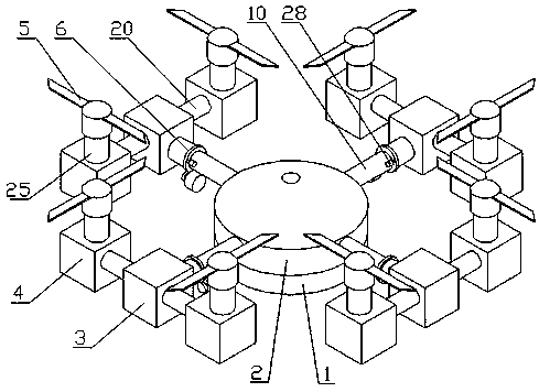
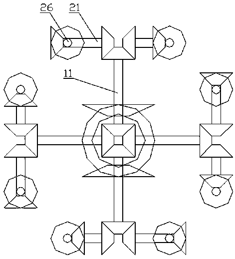
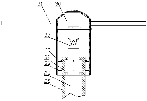
[0021] As shown in the drawings, the present invention includes an engine 1, a first transfer case 2, a second transfer case 3, a third transfer case 4, a rotor tilting device 5 and a transmission shaft tilting device 6, and the first transfer case Four first transmission shaft arms 10 are arranged in cross symmetry on the box 2, and first transmission shafts 11 are respectively arranged in the four first transmission shaft arms 10, and the output shaft of the engine 1 drives four transmission shafts through the first transfer case 2 gears. The first transmission shaft 11 rotates; the output end of the first transmission shaft arm 10 is provided with a second transfer case 3, and the second transfer case 3 is symmetrically provided with two second transmission shaft arms 20, and the two second transmission shafts The second transmission shaft 21 is respectively arranged in the arm 20, and the output end of the first transmission shaft 11 drives two second transmission shafts 21...


PUM


Abstract

The invention discloses a multi-shaft multi-direction tilting type multi-rotor aircraft transmission system. The transmission system comprises an engine (1), a first transfer case (2), a second transfer case (3), a third transfer case (4), a rotor wing tilting device (5) and a transmission shaft tilting device (6). Four first transmission shaft arms (10) are symmetrically arranged on the first transfer case (2) in a crossed manner, the first transmission shafts (11) are arranged in the four first transmission shaft arms (10) respectively, and an output shaft of the engine (1) drives the four first transmission shafts (11) to rotate through the gears of the first transfer case (2). The second transfer case (3) is arranged at the output end of each first transmission shaft arm (10), two second transmission shaft arms (20) are symmetrically arranged on the second transfer case (3), and the second transmission shafts (21) are arranged in the two second transmission shaft arms (20) respectively. The vertical take-off and landing of the rotorcraft can be achieved, and the advantages of flexibility, maneuverability, stability and the like of a tilting rotorcraft and a multi-rotor unmannedaerial vehicle are achieved.

Description

technical field [0001] The invention relates to the technical field of aircraft, in particular to a transmission system of a multi-axis, multi-directional tilting multi-rotor aircraft. Background technique [0002] At present, rotary-wing helicopters or rotary-wing UAVs that can be applied to low-airspace flight such as rescue and emergency rescue, delivery and transportation, and survey aerial photography can take off and land vertically, and hover accurately over specific positions to perform necessary work. Most of the designs of rotorcraft use a power unit to drive a rotor to provide flight lift for the aircraft, such as single-rotor, multi-rotor, and tilt-rotor aircraft; single-rotor aircraft are generally fuel-powered helicopters. Airplanes have long propeller blades and heavy take-off weight, but the downflow generated by the rotor is partially blocked by the fuselage, resulting in high energy consumption, low stability and safety, and take-off is often restricted by ...

Claims


Application Information

Patent Timeline
Patent Type & Authority Applications(China)
IPC IPC(8): B64C27/08B64C29/00B64C27/52
CPCB64C27/08B64C29/00B64C27/52
Inventor 吴华锋
Owner 吴华锋
Learn More