A sponge-type gully construction structure

A technology of gullies and sponges, applied to drainage structures, buildings, waterway systems, etc., can solve the problems of rainwater passing through, unable to control the drainage of sewers, etc., and achieve the effect of water storage

Active Publication Date: 2020-09-15
皖建生态环境建设有限公司
View PDF11 Cites 0 Cited by
  • Summary
  • Abstract
  • Description
  • Claims
  • Application Information

AI Technical Summary

Problems solved by technology

[0004] In view of this, the purpose of the present invention is to provide a sponge-type gully construction structure to solve the technical problems in the prior art that the sewer drainage cannot be controlled according to the rainfall and the rainwater can pass through the filter device with suitable mesh holes.

Method used


Image

  • A sponge-type gully construction structure
  • A sponge-type gully construction structure
  • A sponge-type gully construction structure

Examples


Embodiment

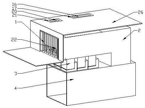
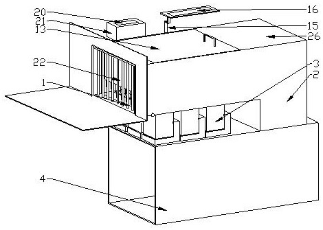
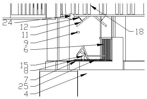
[0026] Embodiment: a kind of sponge type gully construction structure, as Figure 1-5As shown, it includes a vertical grate type grate 1, an upper drain 2 connected to the grate 1, a sponge drainage bin 3 connected to the bottom of the upper drain 2, a main drain 4 connected to the sponge drain 3 and an upper drain In the channel 2 and at the fine screen 5 at the rear of the grate 1 and the sponge drainage bin 3; the direction of rainwater flowing in the upper drain 2 and the main drain 4 is from front to back, and the vertical grate 1 can Preliminary filtration of rainwater before entering the upper drainage channel 2, the upper drainage channel 2 is set above the main drainage channel 4, and the cross-sectional area of ​​the upper drainage channel 2 is smaller than the cross-sectional area of ​​the main drainage channel 4, the displacement in the main drainage channel 4 Larger than the drainage in the upper drainage channel 2, the upper drainage channel 2 is connected to the...


PUM


Abstract

The invention discloses a sponge type gutter inlet building structure which comprises a vertical grate type grate, an upper water discharge passage, a plurality of sponge water discharge cabins, a main water discharge passage and a fine sieve screen, wherein the upper water discharge passage is connected with the grate; the sponge water discharge cabins are connected with the bottom of the upper water discharge passage; the main water discharge passage is connected with the sponge water discharge cabins; the fine sieve screen is arranged in the upper water discharge passage and is positioned at the back part of the grate and the sponge water discharge cabins; the plurality of water sponge water discharge cabins are installed; and the upper water discharge passage and the main water discharge passage are connected, and the connecting position is positioned at the back part of the fine sieve screen. The technical problems that in the prior art, the water discharge quantity of a sewer cannot be controlled according to the rainfall capacity, and the rainwater cannot be controlled to pass a filter device with proper sieve holes are solved.

Description

technical field [0001] The invention relates to a drainage system, in particular to a construction structure of a sponge-type gully. Background technique [0002] The rainwater outlet refers to the facility for the pipeline drainage system to collect surface water. It is a structure that collects rainwater on the rainwater pipe or combined pipe. The channel directly sent to the urban river and lake water system is not only the bottleneck of the urban drainage system to collect rainwater runoff, but also the primary channel for urban non-point source pollutants to enter the water environment. It not only drains water for urban roads, but also replenishes water for urban water bodies. There are two main types of rainwater outlets: flat grate type and vertical grate type. The flat grate type water flow is smooth, but it is easy to be blocked by sundries such as branches during heavy rain, which affects the water collection capacity. The vertical grate type is not easy to blo...

Claims


Application Information

Patent Timeline
Patent Type & Authority Patents(China)
IPC IPC(8): E03F3/00E03F5/04E03F5/06
CPCE03F3/00E03F5/0401E03F5/0404E03F5/06
Inventor 殷情方香林聂爱国袁家玉
Owner 皖建生态环境建设有限公司
Why Eureka
Try Eureka