Punching assembly and punching device

A technology of hole components and fixed components, which is applied in the field of medical devices, can solve the problems of time-consuming, laborious, dangerous, stab wounds, etc., and achieve the effect of increasing the success rate, uniform hole spacing, and good appearance

Pending Publication Date: 2020-09-08
张家港市第一人民医院
View PDF0 Cites 0 Cited by
  • Summary
  • Abstract
  • Description
  • Claims
  • Application Information

AI Technical Summary

Problems solved by technology

But this method is time-consuming and labor-intensive, and at the same time it may be stabbed, which is very dangerous

Method used


Image

  • Punching assembly and punching device
  • Punching assembly and punching device
  • Punching assembly and punching device

Examples


Embodiment 1

[0033] This embodiment specifically elaborates on the punching device used for fixing the wound cover and punching the wound cover. Wound coverings include autologous skin, allogeneic skin, heterogeneous skin, artificial dermis scaffolds and various special dressings, etc., which are used to transplant to the wound surface of the human body during surgery.

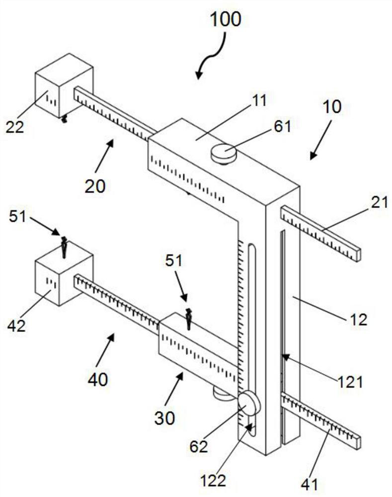
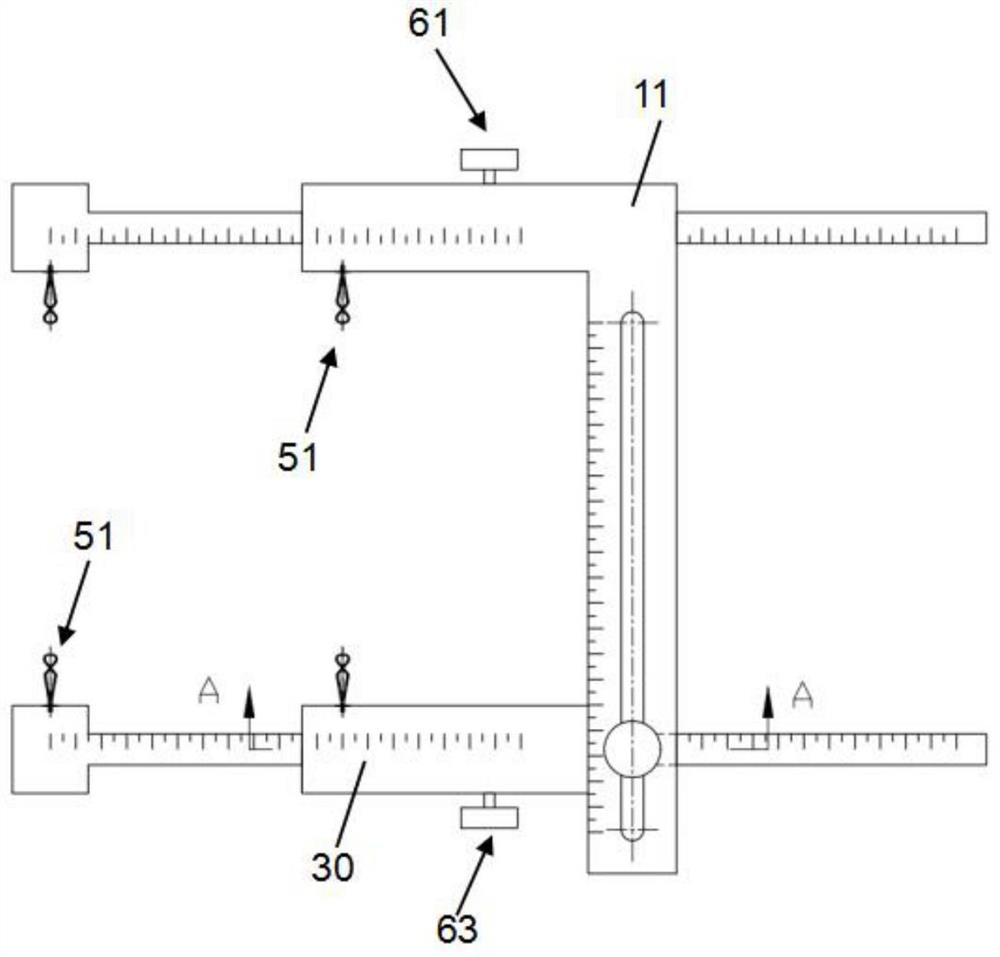
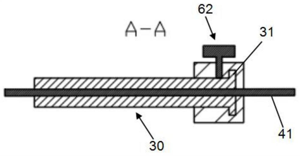
[0034] figure 1 is a structural schematic diagram of the adjustable frame in Embodiment 1 of the present invention, figure 2 is the front view of the adjustable frame in Embodiment 1 of the present invention, image 3 yes figure 2 The A-A profile in the, Figure 4 It is a schematic structural view of the handkerchief clip in Embodiment 1 of the present invention, Figure 5 is a schematic structural view of the punching assembly in Embodiment 1 of the present invention.

[0035] Such as Figure 1-5 As shown, the punching device includes a fixing component 100 and a punching component 200 .

[0036] The fixing assem...

Embodiment 2

[0079] In this embodiment, the same numbers are given to the same structures as in Embodiment 1, and these structures have the same functions and effects as in Embodiment 1, and will not be repeated here.

[0080] The punching device of this embodiment includes a fixing assembly 100 and a punching assembly 300 , the structure of the fixing assembly 100 is the same as that of Embodiment 1, and will not be repeated here.

[0081] Figure 6 It is a structural schematic diagram of the punching assembly in Embodiment 2 of the present invention.

[0082] Such as Figure 6 As shown, the punching assembly 300 includes a tool holder 201 , an adjusting plate 302 and a distance locking member 203 .

[0083]One end of the adjusting plate 302 is fixed on the fixed arm 213 by a rivet, and the other end is detachably connected to the moving arm 214 by a distance locking member 203 . Along the extending direction of the adjusting plate 302 , an adjusting groove 303 penetrating up and down ...

Embodiment 3

[0091] In this embodiment, the same numbers are assigned to the same structures as those in Embodiments 1 and 2. These structures have the same functions and effects as those in Embodiment 2, and will not be repeated here.

[0092] The punching device of this embodiment includes a fixing assembly 100 and a punching assembly 400 , the structure of the fixing assembly 100 is the same as that of Embodiment 1, and will not be repeated here.

[0093] Figure 7 It is the structural representation of the perforated assembly in embodiment 3; Figure 8 yes Figure 7 A partial enlargement of the .

[0094] Such as Figure 7 , 8 As shown, the punching assembly 400 and the punching assembly 300 include a tool holder 201 , an adjusting plate 401 , a distance locking member 203 and a corrugated clamping plate 402 .

[0095] One end of the adjusting plate 401 is fixed on the fixed arm 213 by a rivet, and the other end is detachably connected to the moving arm 214 by the distance locking...


PUM


Abstract

The invention belongs to the technical field of medical instruments, and particularly relates to a punching assembly and a punching device. The punching device comprises a fixing assembly used for fixing a wound covering and a punching assembly used for punching the wound covering; the punching assembly comprises a knife rest, an adjusting plate and a distance locking piece; the knife rest comprises a fixed arm used for installing and fixing a puncture piece and a movable arm used for installing and moving the puncture piece; one end of the adjusting plate is connected with the fixed arm; andthe other end of the adjusting plate is connected with the movable arm through a distance locking piece. Due to the fact that the distance locking piece can fix the movable arm to different positionsof the adjusting plate, the distance between the fixed puncture piece and the movable puncture piece can be adjusted, and the distance between the fixed puncture piece and the movable puncture piece can be adjusted according to needs. A user can hold the punching assembly by hand to punch a wound covering, and the wound covering with evenly distributed holes is obtained. According to the punchingdevice, punching operation can be completed by one person, safety and convenience are achieved, the hole distance is uniform, and the appearance effect of postoperative wound coverings is good.

Description

technical field [0001] The invention belongs to the technical field of medical instruments, and in particular relates to a punching assembly and a punching device. Background technique [0002] Various wound coverings are often used in wound repair surgery, including autologous skin, allogeneic skin, heterogeneous skin, artificial dermal scaffolds, and various special dressings. Due to their biological or material characteristics, these wound coverings are not permeable, which often causes blood and fluid accumulation in the human tissue under the covering and infection. In severe cases, the covering will dissolve and fall off as a whole, resulting in failure of wound repair or even infection. Diffusion aggravates the condition. In clinical use, it is necessary to punch holes in various wound coverings to facilitate the drainage of blood and fluid under the coverings. The usual method is that 2-3 surgical personnel hold or clamp the wound coverings, and then use a scalpel b...

Claims


Application Information

Patent Timeline
IPC IPC(8): A61M27/00B26F1/02
CPCA61M27/00B26F1/02
Inventor 季佳浩常菲倪佳敏尹希黄晓丰钱李科李虎钱明元
Owner 张家港市第一人民医院
Why Eureka
Try Eureka