
Prefabricated laminated slab design method, assembly and disassembly method and prefabricated laminated slab

A design method and technology of laminated slabs, applied in floor slabs, instruments, electrical digital data processing, etc., can solve the problems of scattered sizes and various varieties, and achieve the effects of reducing the number of mold openings, improving construction efficiency, standardization and utilization

Pending Publication Date: 2021-11-05
SHANGHAI JOHNSON ARCHITECTURAL & ENG DESIGN CONSULTANTS
View PDF13 Cites 2 Cited by
  • Summary
  • Abstract
  • Description
  • Claims
  • Application Information

AI Technical Summary

Problems solved by technology

[0004] The purpose of the present invention is to provide a design method, assembly and disassembly method and prefabricated laminated slabs, which can realize the standardization of prefabricated laminated slabs, solve the problems of scattered width and variety of prefabricated laminated slabs, and improve the efficiency of molds. Utilization rate, reduce the number of mold openings in the factory, save mold and engineering costs, reduce the construction difficulty of prefabricated laminated panels, and improve construction efficiency

Method used


Image

  • Prefabricated laminated slab design method, assembly and disassembly method and prefabricated laminated slab
  • Prefabricated laminated slab design method, assembly and disassembly method and prefabricated laminated slab
  • Prefabricated laminated slab design method, assembly and disassembly method and prefabricated laminated slab

Examples


Embodiment Construction

[0041] In order to more clearly illustrate the embodiments of the present invention or the technical solutions in the prior art, the specific implementation manners of the present invention will be described below with reference to the accompanying drawings. Obviously, the accompanying drawings in the following description are only some embodiments of the present invention, and those skilled in the art can obtain other accompanying drawings based on these drawings and obtain other implementations.

[0042] In order to make the drawing concise, each drawing only schematically shows the parts related to the present invention, and they do not represent the actual structure of the product. In addition, to make the drawings concise and easy to understand, in some drawings, only one of the components having the same structure or function is schematically shown, or only one of them is marked. Herein, "a" not only means "only one", but also means "more than one".

[0043] It should ...


PUM


Abstract

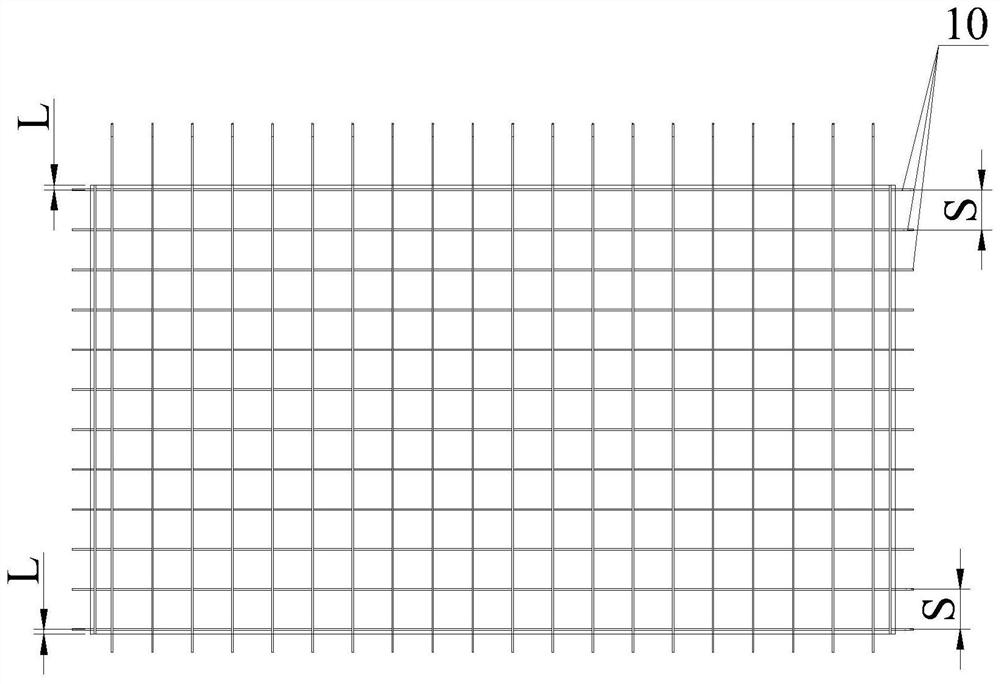
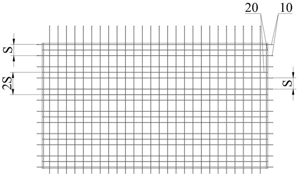
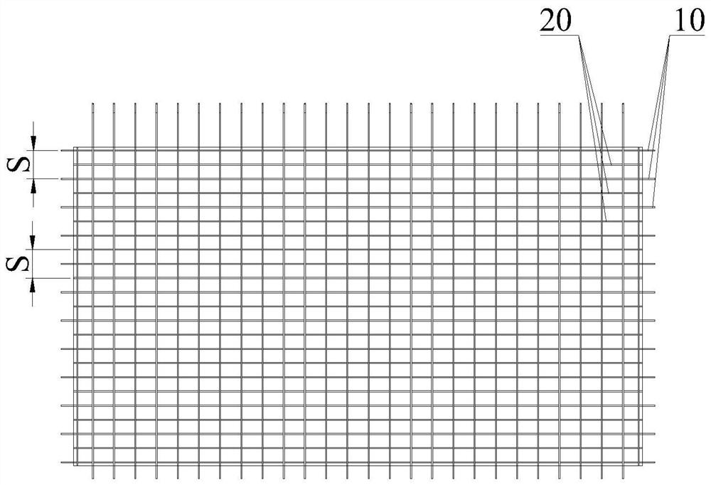
The invention belongs to the field of prefabricated buildings, and discloses a prefabricated laminated slab design method, an assembly and disassembly method and a prefabricated laminated slab. The design method comprises the following steps: selecting a distance S as a rib outlet distance of the prefabricated laminated slab; adopting an equal-strength substitution formula to unify the spacing of the steel bars of the prefabricated laminated slab to be S, 0.75 S or 0.5 S; when the distance between the reinforcing steel bars of the prefabricated laminated slab is S, the reinforcing steel bars entering the support are arranged according to the distance S; when the distance between the reinforcing steel bars of the prefabricated laminated slab is 0.75 S, firstly arranging the reinforcing steel bars with the reinforcing steel bars being exposed according to the distance S, and then arranging one reinforcing steel bar without reinforcing steel bars between every two reinforcing steel bars with the reinforcing steel bars being exposed every 2S; and when the distance between the reinforcing steel bars of the prefabricated laminated slab is 0.5 S, firstly arranging the reinforcing steel bars according to the distance S, and then arranging one non-reinforcing steel bar between every two reinforcing steel bars. By unifying the rib outlet distance, the hole opening distance in the mold is unified, the mold can be repeatedly used, the standardization and utilization rate of the mold are improved, the number of times of factory mold opening is reduced, the mold cost is reduced, and the mold and project manufacturing cost is saved.

Description

technical field [0001] The invention belongs to the technical field of prefabricated buildings, and in particular relates to a design method, an assembly and disassembly method of a prefabricated laminated board and a prefabricated laminated board. Background technique [0002] A building assembled on site by prefabricated components is called a prefabricated building. With the continuous progress and development of modern industrialization, prefabricated buildings have been promoted and applied. [0003] At present, in prefabricated buildings, the prefabricated laminated slab needs to be connected with the support. The spacing and number of steel bars extending into the support of the prefabricated laminated slab are different, that is, the ribs of each prefabricated laminated slab are different. There are many types, low utilization rate of molds, and complex and disorderly construction on site. Not only is it difficult to adapt to the production requirements of standard ...

Claims


Application Information

Patent Timeline
Patent Type & Authority Applications(China)
IPC IPC(8): G06F30/13E04B5/17G06F119/14
CPCG06F30/13E04B5/17G06F2119/14
Inventor 张广成李新华初文荣马海英王招鑫
Owner SHANGHAI JOHNSON ARCHITECTURAL & ENG DESIGN CONSULTANTS
Learn More