
Connecting rod mechanism and engine

A connecting rod mechanism and connecting rod technology, which is applied in the field of automobile engines, can solve the problems of worsening airflow movement and combustion, increasing engine burden, and large motion inertial mass, and achieving the effects of increasing maximum power, convenient control, and small structural changes.

Active Publication Date: 2019-12-27
FAW JIEFANG AUTOMOTIVE CO
View PDF7 Cites 2 Cited by
  • Summary
  • Abstract
  • Description
  • Claims
  • Application Information

AI Technical Summary

Problems solved by technology

Among them, the variable piston height and the variable connecting rod length have the least structural changes to the traditional engine, and the scheme of the additional combustion chamber has a significant impact on the shape of the combustion chamber, thereby deteriorating the airflow movement and combustion; the change of the crankshaft position and the cylinder head The driving devices of the two schemes of relative displacement require a large power output to realize the change of position, thereby increasing the load on the engine, and the original machine has been greatly changed or needs to be redesigned; the multi-link mechanism and the toothed lever can be better Achieve continuous variable and high working stability, but the structure is very complex, the mass of motion inertia is large, and it is not suitable for traditional models, and the engine needs to be redesigned

Method used


Image

  • Connecting rod mechanism and engine
  • Connecting rod mechanism and engine
  • Connecting rod mechanism and engine

Examples


Embodiment Construction

[0026] In order to make the technical problems solved by the present invention, the technical solutions adopted and the technical effects achieved clearer, the technical solutions of the embodiments of the present invention will be further described in detail below in conjunction with the accompanying drawings. Obviously, the described embodiments are only the technical solutions of the present invention. Some, but not all, embodiments. Based on the embodiments of the present invention, all other embodiments obtained by those skilled in the art without making creative efforts belong to the protection scope of the present invention.

[0027] In the description of the present invention, unless otherwise clearly specified and limited, the terms "connected", "connected" and "fixed" should be understood in a broad sense, for example, it can be a fixed connection, a detachable connection, or an integrated ; It can be a mechanical connection or an electrical connection; it can be a d...


PUM


Abstract

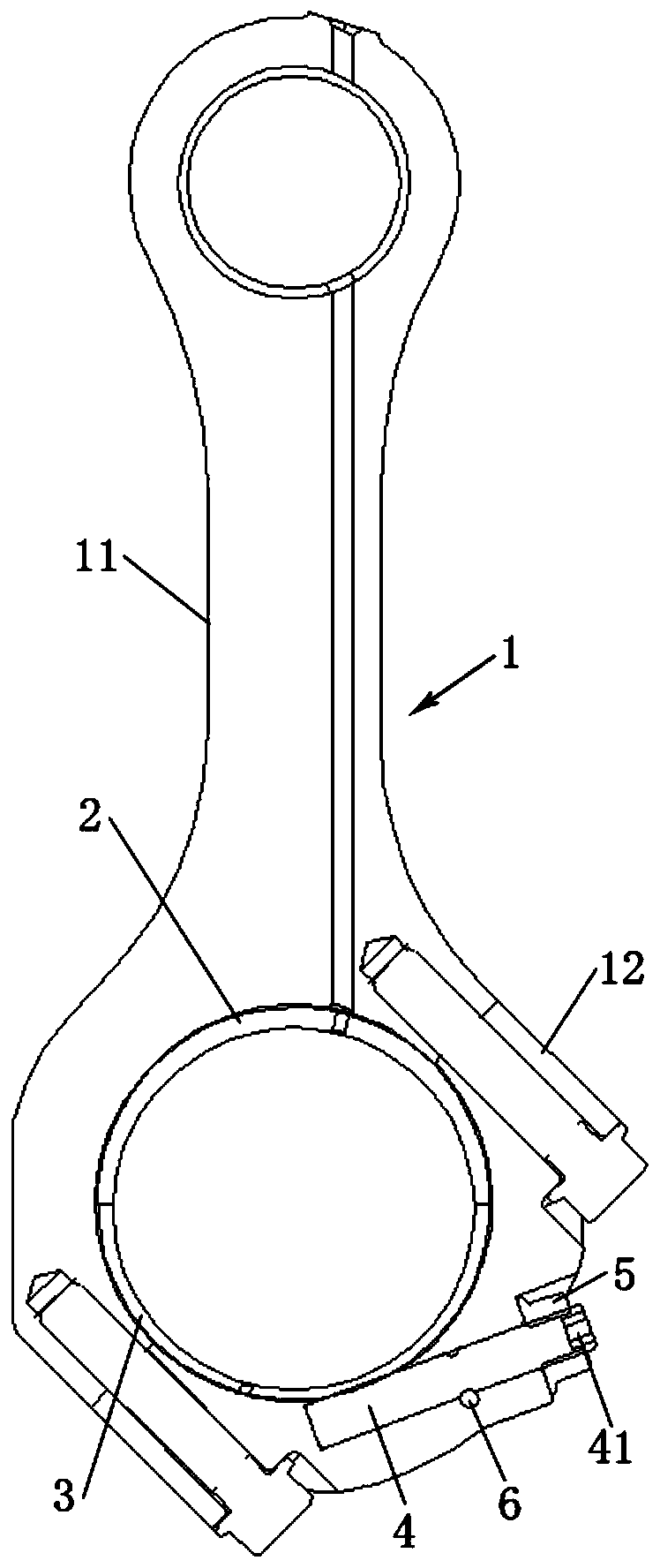
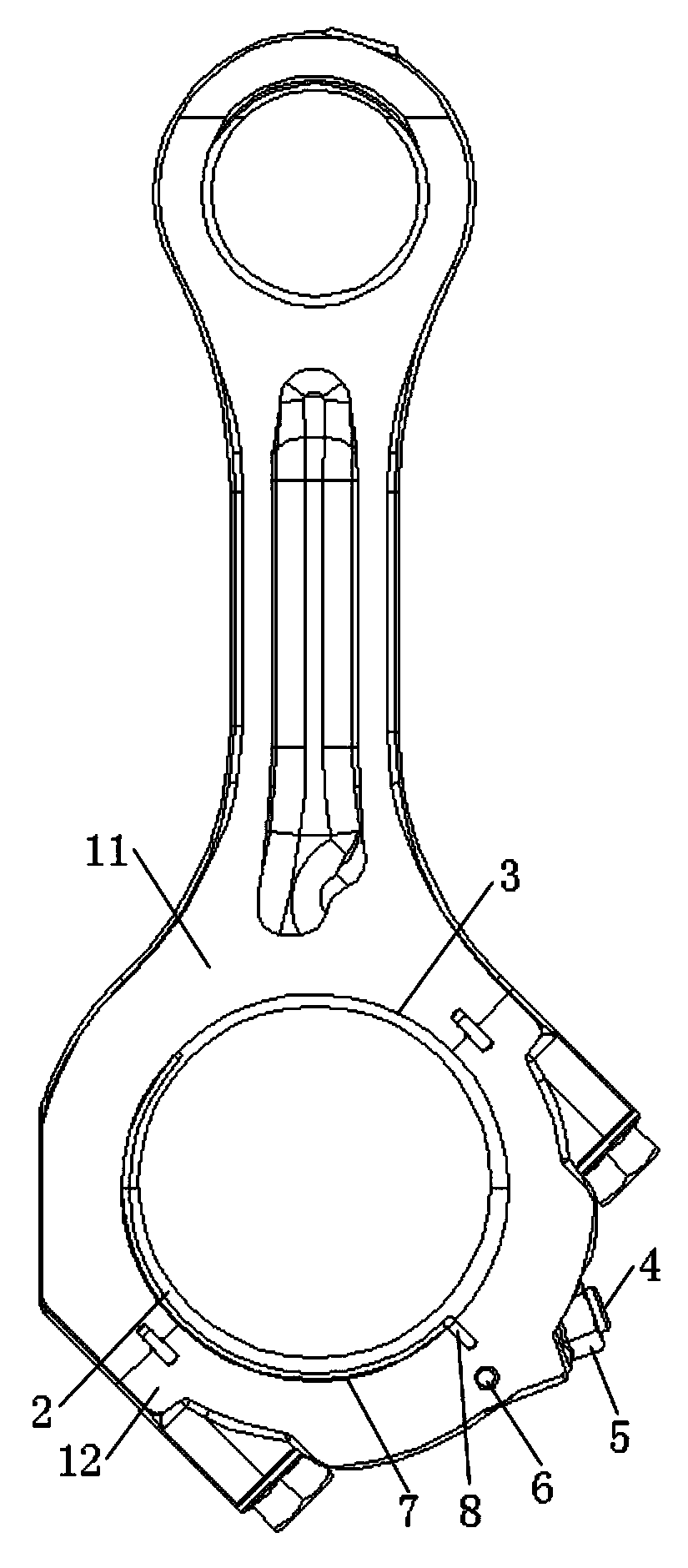
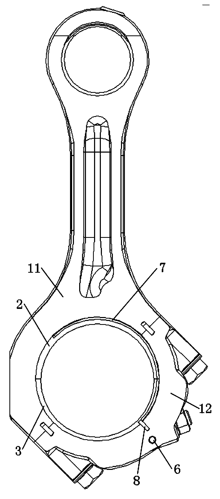
The invention relates to the technical field of automobile engines, and discloses a connecting rod mechanism and an engine. The connecting rod mechanism comprises a connecting rod and an adjusting assembly, wherein a bearing bush assembly is arranged in a large head hole of the connecting rod; the bearing bush assembly comprises an upper bearing bush and a lower bearing bush, wherein the wall thickness of the upper bearing bush is gradually thickened from two ends to the middle, and the wall thickness of the lower bearing bush is gradually thinned from two ends to the middle; and the adjustingassembly is arranged on the connecting rod and used for adjusting the circumferential positions of the upper bearing bush and the lower bearing bush. According to the connecting rod mechanism and theengine, the upper bearing bush and the lower bearing bush in the connecting rod mechanism form an eccentric bearing bush assembly, and the adjusting assembly adjusts the circumferential positions ofthe upper bearing bush and the lower bearing bush, so that the running stroke of the connecting rod is variable, and the requirement for the compression ratio of the engine of different purposes can be met; and in addition, structure changes by the connecting rod mechanism on the engine is small, so that simple structure, convenient control, good reliability and low cost are all achieved.

Description

technical field [0001] The invention relates to the technical field of automobile engines, in particular to a connecting rod mechanism and an engine. Background technique [0002] Variable compression ratio (VCR) technology can be called the last revolution of engine variable technology, which has a great impact on engine performance, can greatly reduce engine fuel consumption and improve emission levels. When the internal combustion engine is running at medium and low speeds, the intake air volume or fuel injection volume is small, and when the maximum pressure or temperature of the compression stroke or power stroke is low, a higher compression ratio is suitable; when the internal combustion engine is running at medium and high speeds, the intake air volume Or when the fuel injection volume is large, when the maximum pressure or temperature of the compression stroke or the power stroke is high, it is suitable to adopt a lower compression ratio, so that the efficiency of th...

Claims


Application Information

Patent Timeline
Patent Type & Authority Applications(China)
IPC IPC(8): F02B75/04F16C7/06
CPCF02B75/045F16C7/06
Inventor 夏少华董效彬马里郑冰樊嘉天张春丰袁宝良朱明健
Owner FAW JIEFANG AUTOMOTIVE CO
Learn More