Press machine

A mechanical and hydraulic cylinder technology, applied in the field of high-speed stamping machinery, can solve the problems of unrealistic, unrecorded slider position control, inability to make the piston move forward and backward at high speed, and achieve the effect of less swing

Pending Publication Date: 2021-03-05
AIDA ENG LTD
View PDF10 Cites 0 Cited by
  • Summary
  • Abstract
  • Description
  • Claims
  • Application Information

AI Technical Summary

Problems solved by technology

[0012] In Patent Document 1, it is described that a hydraulic cylinder is controlled by a hydraulic pump driven by a servo motor, but it is not described to control the position of the slider at a high SPM
In addition, in the hydraulic drive device described in Patent Document 1, there is only one hydraulic pump driven by the servo motor, and it is unrealistic to use one hydraulic pump to operate the hydraulic cylinder at a high SPM.
[0013] In the high-speed stamping machine described in Patent Document 2, the rod of the small-diameter auxiliary cylinder is connected to the piston of the pressure cylinder. When the pressure cylinder is unloaded, the piston advances and retreats at high speed through the auxiliary cylinder. In the case of a small-diameter auxiliary cylinder driven by a pump, it is impossible to make the piston advance and retreat at high speed

Method used


Image

  • Press machine
  • Press machine
  • Press machine

Examples


no. 1 approach

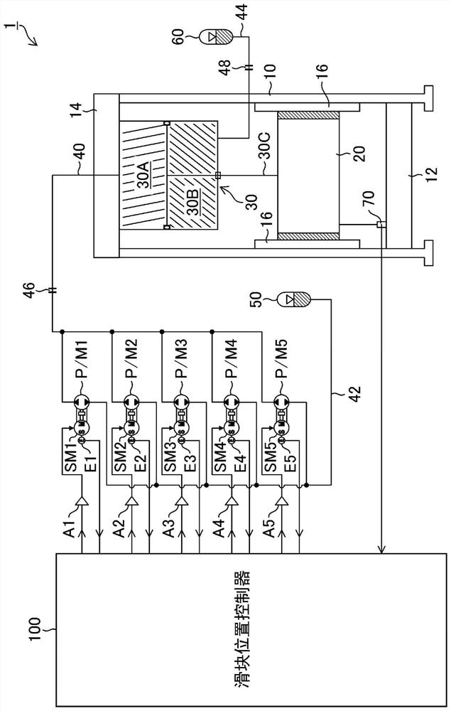
[0078] figure 1 It is a figure which shows 1st Embodiment of the press machine of this invention.

[0079] figure 1 The press machine 1 of the first embodiment shown has a frame composed of a column 10, a base 12, and a crown (frame upper strength member) 14, and the guide 16 provided on the column 10 is used to move the slider 20 in the vertical direction (lead Vertical direction) to guide the way to move freely.

[0080] A hydraulic cylinder (hydraulic cylinder) 30 for driving the slider 20 is fixed to the crown 14 , and a piston rod 30C of the hydraulic cylinder 30 is connected to the slider 20 .

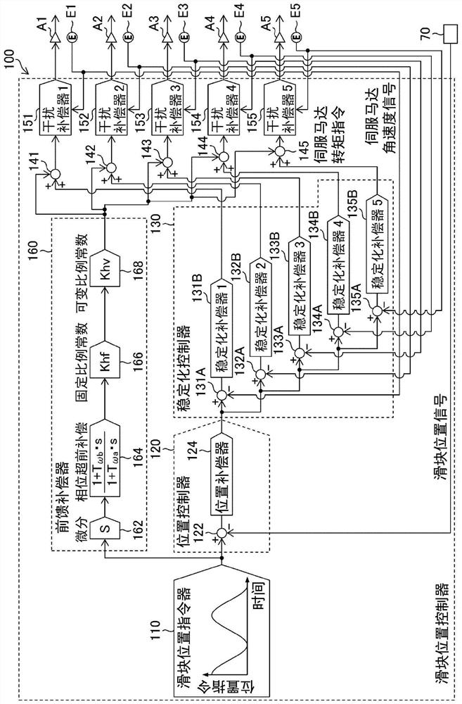
[0081] As the hydraulic device for driving the hydraulic cylinder 30, a plurality of hydraulic pumps / motors (in this example, 5 hydraulic pumps / motors (P / M1 to P / M5)) are provided, and each hydraulic pump / motor A plurality of servomotors (in this example, five servomotors (SM1 to SM5)) are axially connected to the rotation axes of (P / M1 to P / M5).

[0082] One port (first port...


PUM


Abstract

The present invention provides a low-cost press machine in which the amount of swing of a slider during high SPM operation is small. A press machine (1) is provided with: a hydraulic cylinder (30) fordriving a slider (20); a plurality of hydraulic pumps / motors (P / M1 to P / M5) each having a first port connected to a first pressurizing chamber (30A) of the hydraulic cylinder (30); a plurality of servo motors (SM1 to SM5) each connected to a rotating shaft of each hydraulic pump / motor (P / M1 to P / M5); and a slider position controller (100) for controlling the servo motor such that the position ofthe slider is set to a position corresponding to the slider position command signal on the basis of the slider position command signal from the slider position command unit and the slider position signal from the slider position detector (70), the high-pressure accumulator (60) being connected.

Description

technical field [0001] The present invention relates to a press machine, in particular to a high-speed press machine in which the number of strokes per minute (SPM: Shots Per Minute) of a slider is 100 or more. Background technique [0002] When producing IC (Integrated Circuit) lead frames, precision terminals, and other relatively thin precision mass-produced parts with a relatively high SPM of about 100 to 500 SPM, conventionally, mechanical press machines specially suited for high speeds have been used in many cases. . [0003] This type of press machine is composed of a large number of dynamic balance maintaining mechanisms that suppress the swing of the press machine caused by the unbalanced inertial force of the crankshaft and the like under high-speed rotation, and is maintained by the rotation angle between the same bearings as the crankshaft. A special mechanism for maintaining high SPM, such as a special bearing mechanism with a very small gap without unevenness....

Claims


Application Information

Patent Timeline
Patent Type & Authority Applications(China)
IPC IPC(8): B30B15/16B30B1/32B30B15/00
CPCB30B15/16B30B1/32B30B15/0052B30B15/163B30B1/007B30B15/166
Inventor 河野泰幸岩村龙升
Owner AIDA ENG LTD
Why Eureka
Try Eureka