Resistive sensor array readout circuit based on two-wire system equipotential method

A resistive sensor and readout circuit technology, applied in the sensor field, can solve the problems of destroying the ideal isolation feedback condition of the readout circuit, the influence of the test accuracy of the resistive sensor array, and the measurement error of the resistance value of the tested unit, etc. Resistance range, the effect of eliminating interference and eliminating crosstalk error

Inactive Publication Date: 2019-12-27
久耀电子科技(江苏)有限公司
View PDF0 Cites 0 Cited by
  • Summary
  • Abstract
  • Description
  • Claims
  • Application Information

AI Technical Summary

Problems solved by technology

Lead resistances with basically the same resistance and contact resistances with different resistances have a significant impact on the test accuracy of the resistive sensor array
As far as the shared row and column resistive sensor array based on the equipotential method is concerned, the lead resistance and contact resistance cause the potential difference between the drive terminal of the readout circuit and the drive terminal of the resistive sensor array module, and also cause the The potential difference between the sampling terminal of the resistive sensor array module, thus destroying the ideal isolation feedback condition of the readout circuit, and making the resistance measurement error of the unit under test larger
Therefore, basically the same lead resistance and different joint contact resistance have a significant impact on the test results of the shared row and column resistive sensor array based on the equipotential method. At the same time, the channel conduction resistance of the multi-way switch in the traditional method will affect the unit under test. How to eliminate the influence of these factors is a problem to be further studied

Method used


Image

  • Resistive sensor array readout circuit based on two-wire system equipotential method
  • Resistive sensor array readout circuit based on two-wire system equipotential method
  • Resistive sensor array readout circuit based on two-wire system equipotential method

Examples


Embodiment Construction

[0034] The technical scheme of the present invention is described in detail below in conjunction with accompanying drawing:

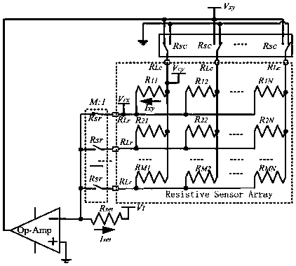
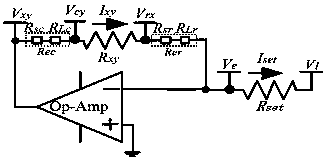
[0035] figure 2 It shows the principle of the equipotential method readout circuit of the existing shared row and column line resistive sensor array, and the current resistive sensor to be tested in the figure R xy for M x N shared row and column resistive sensor array R 11 , image 3 for figure 2 The equivalent diagram of the readout principle of the readout circuit. In this readout circuit, there is only one connection between each row or column line of the array and the test circuit. Under the ideal working condition of the circuit, the channel on-resistance of all the two-to-one multi-way switches of the column lines R sc , the cumulative resistance of the lead resistance of the drive connection line and the contact resistance of the connector R Lc is ignored like this R xy The voltage of the column line V cy =V xy , the voltage ...


PUM


Abstract

The invention discloses a resistive sensor array readout circuit based on a two-wire system equipotential method, and belongs to the technical field of sensors. The readout circuit aims at an M * N two-dimensional resistive sensor array sharing a row line and a column line. The readout circuit comprises a current feedback operational amplifier, a column line driving operational amplifier, a row multiplexer, a column multiplexer, a test current setting resistor, a reference voltage source and two connecting lines which are respectively arranged for each row line and each column line of the resistive sensor array. The invention further discloses a readout method of the readout circuit, and a sensing system. The two-wire system equipotential method is taken as a key technology, so measurementerrors caused by connecting cable lead resistance, cable joint contact resistance and multi-way switch channel conduction resistance can be effectively eliminated, and the measurement precision of the resistive sensor array is greatly improved.

Description

technical field [0001] The invention relates to the technical field of sensors, in particular to a resistive sensor array readout circuit. Background technique [0002] The array sensing device is to combine multiple sensing elements with the same performance according to the structure of a two-dimensional array. It can change or generate corresponding shapes and characteristics by detecting changes in parameters focused on the array. This feature is widely used in biosensing, temperature tactile and thermal imaging based on infrared sensors, etc. [0003] Resistive sensor arrays are widely used in infrared imaging simulation systems, force tactile sensing and temperature tactile sensing. Taking temperature touch as an example, since the temperature sensing device involves the transfer of heat and the perception of temperature, in order to obtain the thermal properties of the object, the device puts forward higher requirements for the temperature measurement accuracy and re...

Claims


Application Information

Patent Timeline
Patent Type & Authority Applications(China)
IPC IPC(8): G01D5/16
CPCG01D5/16
Inventor 赵莉民
Owner 久耀电子科技(江苏)有限公司
Why Eureka
Try Eureka