Tray separation mechanism driven by air cylinder

A pallet separation and cylinder-driven technology, which is used in conveyors, object destacking, packaging, etc., can solve the problems of large equipment space and complex overall structure, and achieve the effect of compact mechanism.

Pending Publication Date: 2019-12-31
苏州西通自动化科技有限公司
View PDF0 Cites 4 Cited by
  • Summary
  • Abstract
  • Description
  • Claims
  • Application Information

AI Technical Summary

Problems solved by technology

[0002] In the process of industrial automation processing, especially for machinery in the packaging industry, in order to improve the automation of production and make the automation equipment place materials in the designated positions of each container, it is necessary to first separate the multi-layered tray boxes layer by layer. In order to facilitate the automatic production operation of the subsequent process, the existing pallet separation mechanisms are mostly driven by motors or driven by screw rods, the overall structure is relatively complicated, and the equipment occupies a large space

Method used


Image

  • Tray separation mechanism driven by air cylinder
  • Tray separation mechanism driven by air cylinder
  • Tray separation mechanism driven by air cylinder

Examples


Embodiment Construction

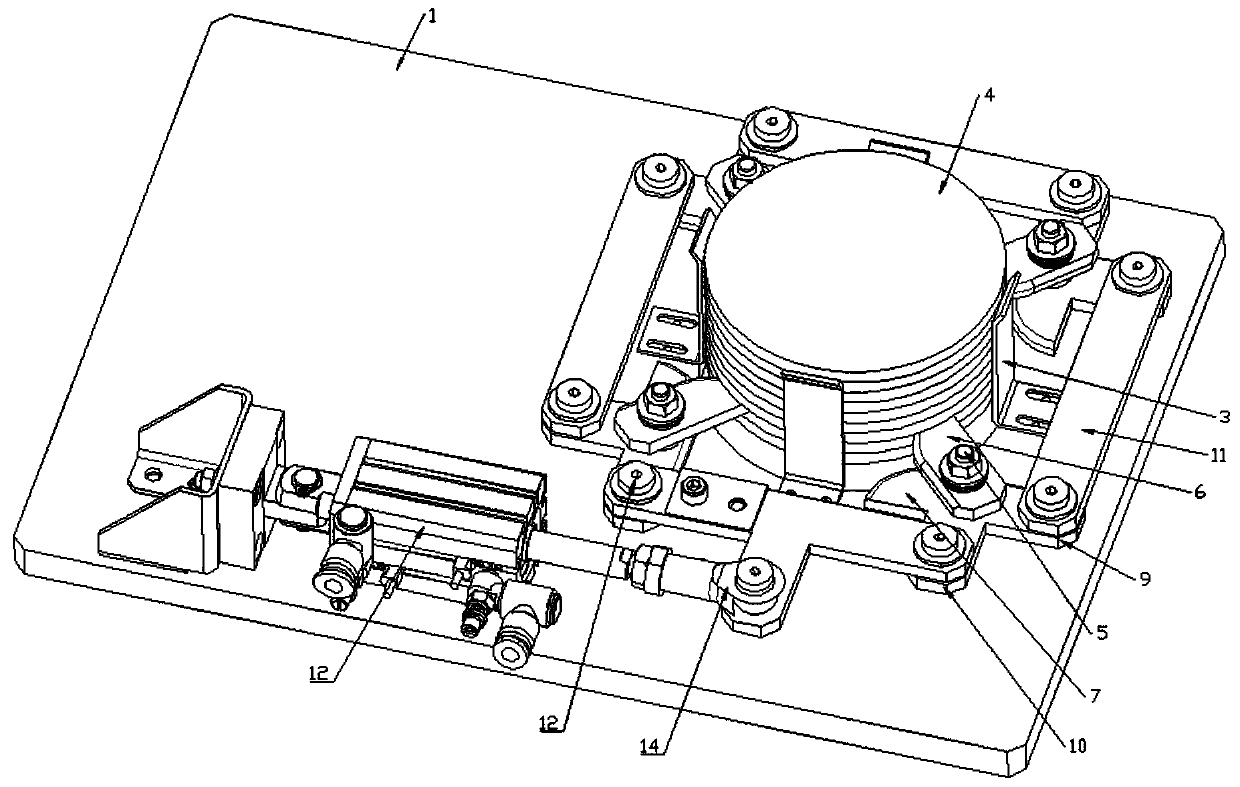
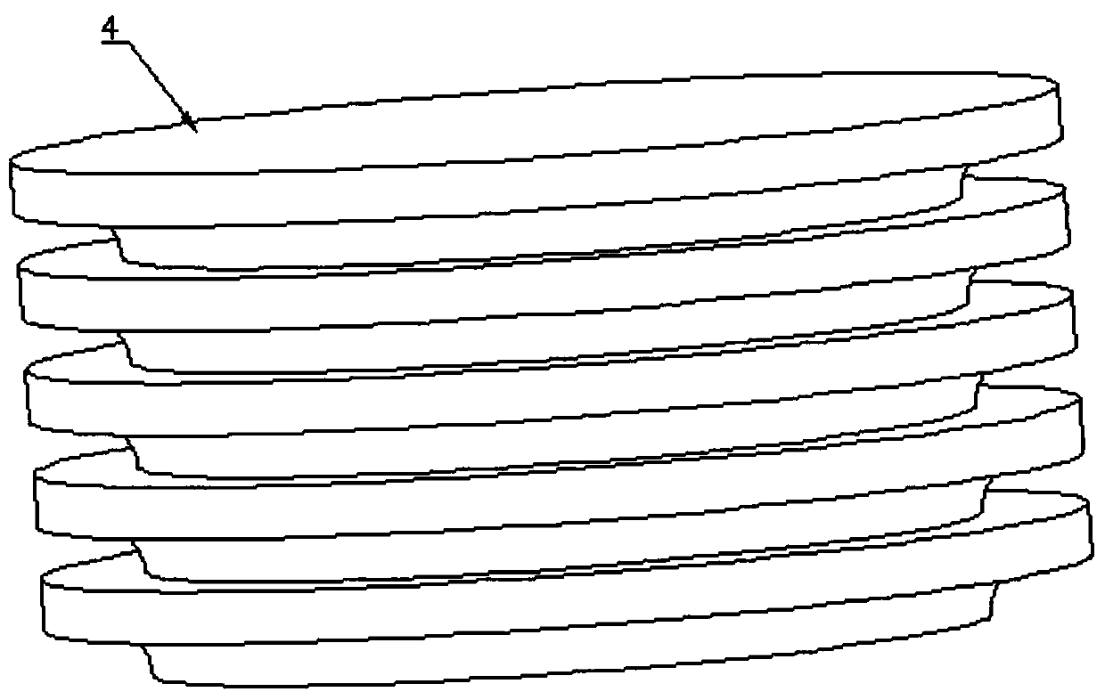
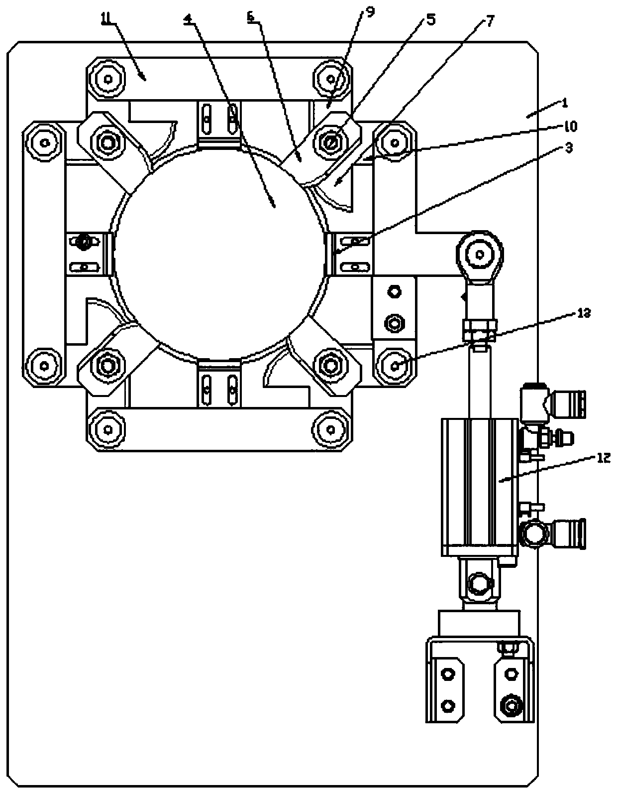
[0023] combine Figure 1 to Figure 9 The cylinder-driven tray separation mechanism shown in this embodiment includes a base plate 1, a drop hole 2 is provided on the base plate 1, and a limit plate 3 is fixed on the periphery of the drop hole 2, and the limit plate 3 will The stacked trays 4 are limited above the inside of the drop hole 2; four stripping assemblies are respectively connected to the substrate 1 through four first rotating shafts 5, and the first rotating shaft 5 rings are arranged on the periphery of the drop hole 2, and The annular axis where it is located is collinear with the axis of the drop hole 2, and the stripping assembly includes a first stripping sheet 6, a second stripping sheet 7 and a spacer 8 arranged between the first stripping sheet 6 and the second stripping sheet 7 , and the height of the pad 8 is set to the height of a tray 4, the first peeling sheet 6 is arranged above the second peeling sheet 7, and one end of the first rotating shaft 5 is ...


PUM


Abstract

The invention provides a tray separation mechanism driven by an air cylinder. The mechanism comprises a baseplate, the baseplate is provided with a falling hole, and limit plates are arranged outsidethe falling hole; four stripping assemblies are further connected to the baseplate through four first rotation shafts respectively, each stripping assembly comprises a first stripping sheet, a secondstripping sheet and a cushion block, the first stripping sheets are arranged above the second stripping sheets, one end of each first rotation shaft is rotatably connected to the baseplate, the firststripping sheets, the cushion blocks and the second stripping sheets are fixedly connected, and when the first stripping sheets and the second stripping sheets are fixed, included angles formed between the first stripping sheets and the second stripping sheets are within 30-60 degrees; the ends of the second stripping sheets extend outwards in the straight line direction to form a first connectionplate and extend outwards in the direction vertical to the straight line to form a second connection plate, and the straight lines where four stripping strips are located are distributed in a rectangular cross mode; the baseplate is further provided with the driving air cylinder for driving the stripping assemblies to rotate back and forth. The tray separation mechanism is compact in structure and more flexible and convenient to use when matched with other mechanisms at random for use.

Description

technical field [0001] The invention relates to a separation mechanism, in particular to a cylinder-driven tray separation mechanism. Background technique [0002] In the process of industrial automation processing, especially for machinery in the packaging industry, in order to improve the automation of production and make the automation equipment place materials in the designated positions of each container, it is necessary to first separate the multi-layered tray boxes layer by layer. In order to facilitate the automatic production operation of the subsequent process, the existing pallet separation mechanism is mostly driven by a motor or driven by a screw rod. The overall structure is relatively complicated, and the equipment occupies a large space. [0003] Therefore, there is an urgent need for a cylinder-driven pallet separation mechanism that is compact in structure, can be used in combination with other mechanisms, and is more flexible and convenient. Contents of ...

Claims


Application Information

Patent Timeline
Patent Type & Authority Applications(China)
IPC IPC(8): B65G59/06B65B43/42
CPCB65B43/42B65G59/066B65G2201/0258
Inventor 杜文泽周益
Owner 苏州西通自动化科技有限公司
Why Eureka
Try Eureka