Coupler box production method

A production method and coupler technology, applied to waveguide devices, connecting devices, electrical components, etc., can solve the problems of low efficiency of coupler boxes

Inactive Publication Date: 2020-07-03
长丰吾道智能光电科技有限公司
View PDF0 Cites 0 Cited by
  • Summary
  • Abstract
  • Description
  • Claims
  • Application Information

AI Technical Summary

Problems solved by technology

The coupler box body is made of aluminum alloy. After the box body is made, it needs to be painted. In the actual painting operation, the outer surface of the installation box a where the wiring hole a1 and the wiring point a2 are located is not painted. operation to avoid the influence of later paint on the electrical conductivity of the coupler. Therefore, before the painting operation, the coupler box needs to be provided with an anti-spray paint label on the above-mentioned wiring hole a1 and the wiring point a2. The above-mentioned wiring points pass through After the automatic labeling operation is completed, after the coupler box is individually exported from the automatic gluing device, the equipment needs to be introduced into the spray booth for painting operation. In order to ensure that the outer surface of the coupler box is evenly sprayed with paint, the stickers need to be The marked coupler box is hung on the hanger. Generally, the position of the hanging hole b1 on the cover b is hung on the hanger, and the couplers are separated from each other, so that it is convenient for the hanger to be hung on the spray paint. In the room, and then manually operate the spray gun to spray paint. After the above-mentioned hanger is sprayed, the coupler box is dried by the drying equipment, and then the coupler box on the hanger is manually dried. Take it out to complete the disassembly of the coupler. The disassembled coupler box is manually removed and disassembled, resulting in low efficiency of the coupler box in actual production.

Method used


Image

  • Coupler box production method
  • Coupler box production method
  • Coupler box production method

Examples


Embodiment Construction

[0038] In order to make the objects and advantages of the present invention clearer, the present invention will be described in detail below in conjunction with the examples. It should be understood that the following words are only used to describe one or several specific implementation modes of the present invention, and do not strictly limit the protection scope of the specific claims of the present invention. As used herein, the terms "parallel" and "perpendicular" are not limited to their strict geometric definitions, but include reasonable and inconsistent tolerances for machining or human error:

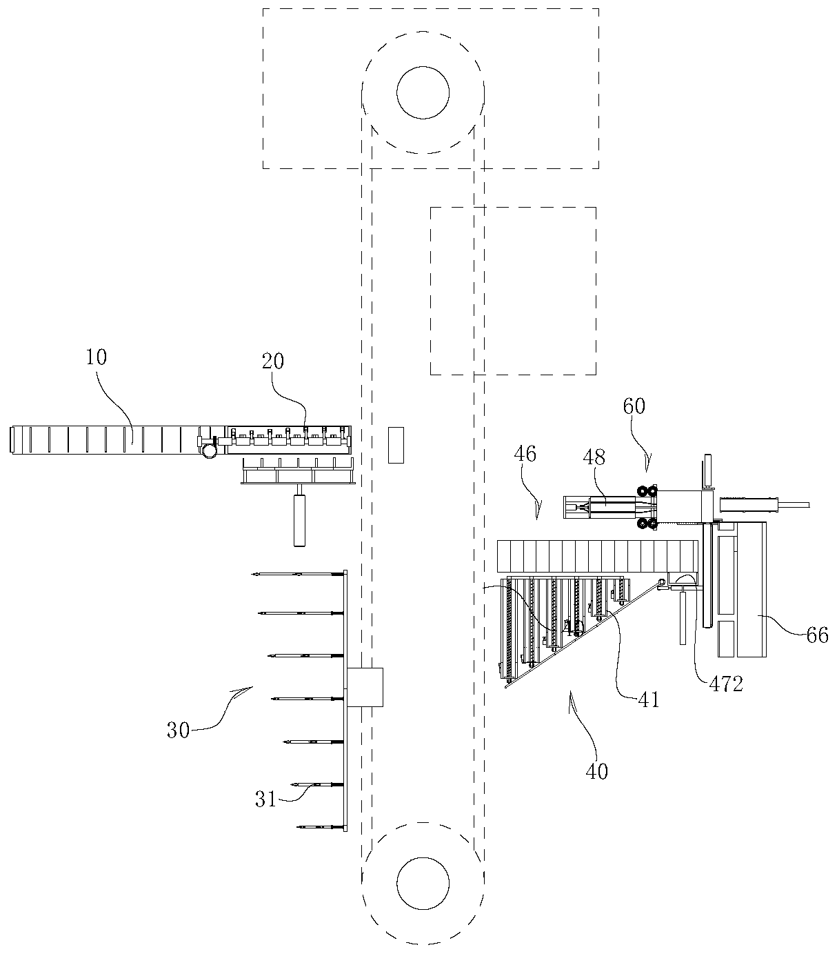
[0039] Attached below Figure 1 to Figure 24 , the coupler box production system of the present invention is described in detail:

[0040] A coupler box production system, comprising a frame body 10 for storing the coupler box body, the exit position of the frame body 10 is provided with a storage table 20, and the coupler box body is located on the upper cover plate of the s...


PUM


Abstract

The invention relates to a coupler box body production method. The method comprises the steps of material receiving, paint spraying and curing; a step of using a bearing frame for bearing a coupler box body of a hanging frame of the paint spraying system; horizontally pushing the coupler box bodies to a material receiving step frame by using a bearing frame, and arranging the coupler box bodies inorder; pushing the coupler box body on the material receiving step frame to an adhesive tape removing device to remove the adhesive tape; transferring the coupler box body with the glue removed to the coupler box body dismounting device to dismount the mounting box and the cover plate, and then separating the mounting box and the cover plate of the coupler box body, so that automation of subsequent production and processing of the coupler box body subjected to paint spraying operation can be realized, and the production efficiency of the coupler box body is improved.

Description

technical field [0001] The invention relates to the technical field of automation equipment, in particular to a production method of a coupler box. Background technique [0002] combine figure 1 with figure 2 As shown, the coupler box of this type is designed to be in the shape of a cuboid as a whole. The box body includes the installation box a and the cover b. The electrical components of the coupler are installed in the installation box a, and at the two ends of the installation box a Wiring holes a1 are respectively provided on the side and the side of the installation box a, and junction points a2 are arranged on the side where the wiring holes a1 are provided on the installation box a. The coupler box body is made of aluminum alloy. After the box body is made, it needs to be painted. In the actual painting operation, the outer surface of the installation box a where the wiring hole a1 and the wiring point a2 are located is not painted. operation to avoid the influe...

Claims


Application Information

Patent Timeline
Patent Type & Authority Applications(China)
IPC IPC(8): H01P11/00H01P5/00
CPCH01P5/00H01P11/00
Inventor 曹茂兵刘长胜郑梦云刘逸云
Owner 长丰吾道智能光电科技有限公司
Why Eureka
Try Eureka