Camera control method, device, terminal equipment and storage medium

A technology of terminal equipment and a control method, which is applied in the direction of TV, color TV parts, TV system parts, etc., can solve the problems of affecting the photographing effect and reducing the user experience, so as to improve the photographing effect, enhance the user experience, and avoid bright spot effect

Active Publication Date: 2021-08-06
WINGTECH COMM
View PDF9 Cites 0 Cited by
  • Summary
  • Abstract
  • Description
  • Claims
  • Application Information

AI Technical Summary

Problems solved by technology

Existing electronic devices mainly use the rear camera to take pictures. When the light conditions are not good, the flash is used to fill in the light. However, when using the flash to fill in the light, especially when taking pictures at close range, it is often in the middle of the photo. There is a large bright spot in the area, which seriously affects the photo effect and greatly reduces the user experience

Method used


Image

  • Camera control method, device, terminal equipment and storage medium
  • Camera control method, device, terminal equipment and storage medium
  • Camera control method, device, terminal equipment and storage medium

Examples


Embodiment 1

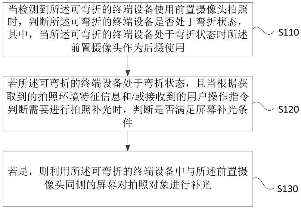
[0027] Figure 1A It is a flow chart of a photographing control method provided by Embodiment 1 of the present invention. This embodiment is applicable to the case where a bendable terminal device is bent and the front camera is used as a rear camera. This method can be implemented by the embodiment of the present invention. This device can be implemented by software and / or hardware, and integrated in the bendable terminal device. Typically, it can be integrated in the central processing unit of the bendable terminal device in the form of program code In the Central Processing Unit (CPU), the method specifically includes the following steps:

[0028] S110. When it is detected that the bendable terminal device uses the front camera to take a picture, determine whether the bendable terminal device is in the bent state, wherein, when the bendable terminal device is in the bent state When the front camera is used as a rear camera.

[0029] In the embodiment of the present inventi...

Embodiment 2

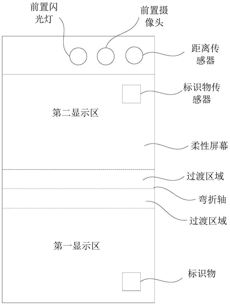
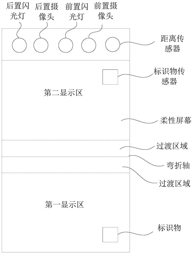
[0055] figure 2 It is a structural block diagram of a camera control device provided in Embodiment 2 of the present invention, and the device specifically includes: a bending state judgment module 210 , a screen fill light condition judgment module 220 and a screen fill light execution module 230 .

[0056] The bending state judging module 210 is configured to judge whether the bendable terminal device is in a bent state when it is detected that the bendable terminal device uses a front camera to take pictures, wherein, when the bendable terminal device When the terminal device is in a bent state, the front camera is used as a rear camera;

[0057] The screen supplementary light condition judging module 220 is used for if the bendable terminal device is in a bent state, and when it is judged that supplementary light for photographing is required according to the acquired photographing environment feature information and / or the received user operation instruction , to determi...

Embodiment 3

[0076] image 3 It is a schematic structural diagram of a device provided by Embodiment 3 of the present invention. image 3 A block diagram of an exemplary device 12 suitable for use in implementing embodiments of the invention is shown. image 3 The shown device 12 is only an example and should not impose any limitation on the functions and scope of use of the embodiments of the present invention.

[0077] Such as image 3 As shown, device 12 takes the form of a general purpose computing device. Components of device 12 may include, but are not limited to: one or more processors or processing units 16, system memory 28, bus 18 connecting various system components including system memory 28 and processing unit 16.

[0078] Bus 18 represents one or more of several types of bus structures, including a memory bus or memory controller, a peripheral bus, an accelerated graphics port, a processor, or a local bus using any of a variety of bus structures. These architectures inclu...


PUM


Abstract

The embodiment of the present invention discloses a photographing control method, device, terminal device and storage medium. The method includes: when it is detected that the bendable terminal device uses the front camera to take pictures, judging that the bendable terminal device Whether the device is in a bent state, wherein, when the bendable terminal device is in a bent state, the front camera is used as a rear camera; if the bendable terminal device is in a bent state, and the screen meets the For supplementary light conditions, the screen on the same side as the front camera in the bendable terminal device is used to provide supplementary light to the subject to be photographed. According to the technical solution of the embodiment of the present invention, when the bendable terminal device is in the bent state and satisfies the screen fill-in light condition, the photographed object is supplemented with light through the screen on the same side as the front camera, avoiding the need for supplementary light from the flashlight. The light causes a bright spot in the middle area of ​​the photo, which improves the photo effect of the bendable terminal device.

Description

technical field [0001] Embodiments of the present invention relate to electronic equipment technology, and in particular, to a photographing control method, device, terminal equipment, and storage medium. Background technique [0002] With the rapid development of electronic technology, a variety of smart terminals have gradually come into people's sight, and terminal equipment with bending function has also become an important branch, providing users with different functions from traditional flat terminal equipment. user experience. [0003] As an important part of electronic terminal equipment, a good photo effect has become one of the decisive factors for evaluating the performance of the equipment. Existing electronic devices mainly use the rear camera to take pictures. When the light conditions are not good, the flash is used to fill in the light. However, when using the flash to fill in the light, especially when taking pictures at close range, it is often in the midd...

Claims


Application Information

Patent Timeline
Patent Type & Authority Patents(China)
IPC IPC(8): H04N5/232H04N5/235
CPCH04N23/61H04N23/62H04N23/631H04N23/74
Inventor 张昱陈磊罗方丁
Owner WINGTECH COMM
Why Eureka
Try Eureka