
A high-voltage damping wire core dip equipment

A damping line and liquid medicine technology, which is applied to the device and coating of the surface coating liquid, which can solve the problems of low coating uniformity, error, power consumption, etc.

Active Publication Date: 2021-03-16
安徽雷上车业部件股份有限公司
View PDF8 Cites 0 Cited by
  • Summary
  • Abstract
  • Description
  • Claims
  • Application Information

AI Technical Summary

Problems solved by technology

[0002] The high-voltage damping wire uses multiple superimposed aramid filaments as the wire core. Before the wire core is wrapped with an insulating layer, it is necessary to uniformly coat the outer surface of the wire core with a potion made of magnetic powder, silica gel and vulcanizing agent. The work of coating liquid medicine requires manual operation, which wastes manpower, and manual operation has large errors, and the coating uniformity is low; or the machine is used instead of manual coating, the machine needs to consume electricity and waste energy, and the purchase can be carried out Machines for coating operations that require substantial cost

Method used

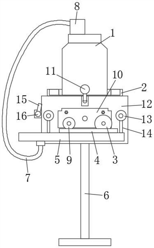
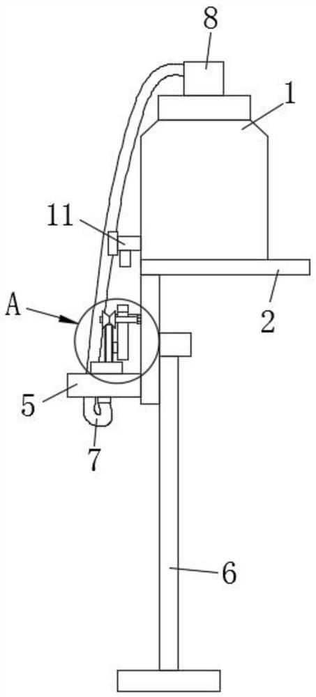
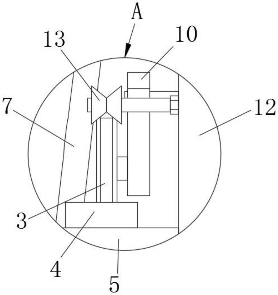

Image

  • A high-voltage damping wire core dip equipment
  • A high-voltage damping wire core dip equipment
  • A high-voltage damping wire core dip equipment

Examples


Embodiment 1

[0029] refer to figure 1 and figure 2 , this embodiment discloses a high-voltage damping wire core dipping device, including a bracket 6, a panel 12 whose surface is parallel to the direction of the high-voltage damping wire, a potion wheel set and a potion disc set rotatably connected to the panel 12. The panel 12 is mounted on the top of the bracket 6 . The medicine tray group is fixed on the panel 12 . The potion wheel set is arranged above the potion pan set. The bottom of the potion wheel set goes deep into the potion pan set. The high-pressure damping wire snaps into the wheel groove of the liquid medicine wheel set.

[0030] The bottom of the potion wheel group goes deep into the potion tray group, so that the wheel groove of the potion wheel group is stained with potion, and the high-pressure damping wire is stuck in the wheel groove of the potion wheel group. When the high-pressure damping line advances along the production line, it passes through the potion whee...

Embodiment 2

[0042] refer to Figure 5 The difference between the second embodiment and the first embodiment is that the wiper cover 17 is also included. The wiper cover 17 is arranged above the outer liquid medicine pan 5 . The wiper cover 17 is fixed on the outlet end of the panel 12 . The aperture of the wiper sleeve 17 is slightly larger than the wire diameter of the high-voltage damping wire. The axis of the high-voltage damping wire is the same as that of the wiper sleeve 17 .

[0043] When the high-voltage damping wire passes through the wiper sleeve 5, because of its aperture slightly larger than the high-voltage damping wire, the excess liquid medicine will be scraped off and dropped into the outer liquid medicine pan 5, and recycled through the return pipe 7, and the axis of the high-voltage damping wire is in contact with the wiper The axes of the water jackets 17 are the same, which can ensure that the liquid medicine is evenly coated on the outer surface of the high-voltage...


PUM


Abstract

The invention discloses a high-pressure damping line core liquid medicine dipping device. The liquid medicine dipping device comprises a support, a plate surface, a panel which is parallel to the linefeeding direction of a high-pressure damping line, a liquid medicine wheel group and a liquid medicine disc group which are rotationally connected to the panel; the panel is mounted at the top end ofthe support; the liquid medicine disc group is fixed on the panel; the liquid medicine wheel group is arranged above the liquid medicine disc group; the bottom of the liquid medicine wheel group penetrates into the liquid medicine disc group; the high-pressure damping line is clamped into a wheel groove of the liquid medicine wheel group. According to the high-pressure damping line core liquid medicine dipping device, the high-pressure damping line is coated with liquid medicine, manual or machine active coating is not needed, the traction power of the production line is fully utilized, the energy is saved, the device is simple in structure and low in cost.

Description

technical field [0001] The invention relates to the technical field of dipping the core of a high-voltage damping wire with liquid medicine, in particular to a device for dipping the core of a high-voltage damping wire with liquid medicine. Background technique [0002] The high-voltage damping wire uses multiple superimposed aramid filaments as the wire core. Before the wire core is wrapped with an insulating layer, it is necessary to uniformly coat the outer surface of the wire core with a potion made of magnetic powder, silica gel and vulcanizing agent. The work of coating liquid medicine requires manual operation, which wastes manpower, and manual operation has large errors, and the coating uniformity is low; or the machine is used instead of manual coating, the machine needs to consume electricity and waste energy, and the purchase can be carried out Machines for coating operations require substantial costs. Contents of the invention [0003] The technical problem to...

Claims


Application Information

Patent Timeline
Patent Type & Authority Patents(China)
IPC IPC(8): B05C3/132B05C11/10
CPCB05C3/125B05C11/1039
Inventor 邵泽伟
Owner 安徽雷上车业部件股份有限公司
Learn More