
Portable pneumatic puller

A portable, air hammer technology, used in hand-held tools, manufacturing tools, etc., can solve the problems of large volume, low efficiency, inconvenient operation, etc., and achieve the effect of flexible working space, improved efficiency and compact structure

Pending Publication Date: 2020-01-03
PLA NO 5719 FACTORY
View PDF2 Cites 0 Cited by
  • Summary
  • Abstract
  • Description
  • Claims
  • Application Information

AI Technical Summary

Problems solved by technology

Since most of the current pneumatic pin pullers are only a simple manual pry and puller, such as: a utility model of a pneumatic pin puller (CN208358690U) proposes a mechanism that pushes the impact hammer through the airflow to pull out the pin; The utility model pneumatic pin puller (CN202010991) provides a fixed station through the handle to control the air inlet of the device, so as to realize the mechanism of manually controlling the impact hammer to pull out the pin. Cancellation process
In addition, because some thin-walled parts need to be involved in the actual application process, such as the disassembly of aero-engine parts, this type of pneumatic puller only completes a pin-pulling process, and cannot control the pin-pulling force and pin-pulling stroke. And the volume is large, it is inconvenient to operate, so it cannot meet the maintenance needs of aero-engines
[0003] At present, the pin removal work in the engine repair process mainly uses special prying tools and pulling tools for master workers. The strength of these devices is uncontrollable, and it is easy to cause damage to engine parts during use, and these damages are not allowed

Method used


Image

  • Portable pneumatic puller
  • Portable pneumatic puller
  • Portable pneumatic puller

Examples


specific Embodiment

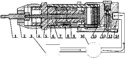
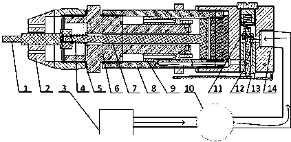
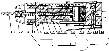
[0025] Specific embodiment: when the puller feeds gas, as Figure 1~2 As shown, the switch handle 13 presses the switch lever 12, so that the pressure gas in the air inlet of the sleeve 14 flows into the air inlet of the main body 8, and the pressure gas in the air inlet of the main body 8 pushes the air hammer 9 to move to the left. When the air hammer 9 movement to figure 2 position, the air inlet hole of the main body 8 is connected with the air hole of the air hammer 9, and the pressure gas enters the inner cavity of the main body 8. Since the pressure surface on the left side of the air hammer 9 is much larger than the pressure area on the right side of the air hammer 9, the air hammer 9 quickly moves to the right. Move, when the pressure gas in the inner cavity of the main body 8 disappears, the air hammer 9 will continue to move to the right due to inertia and hit the pulling shaft 7, and release the pressure gas at the same time, the pulling shaft 7 drives the pulling...


PUM


Abstract

The invention discloses a portable pneumatic puller. The portable pneumatic puller comprises a pulling head, a housing, a gas source, a spring I, a connecting sleeve, a pulling shaft, a main body, a pneumatic hammer, a pressure regulating valve, springs II, a switch lever and a sleeve, wherein the springs II are arranged in the switch lever and the sleeve, the housing is connected with the connecting sleeve, the air source is connected with one end of the sleeve through the pressure regulating valve, the other end of the sleeve communicates with a gas inlet hole of the main body, the gas inlethole of the main body communicates with the pneumatic hammer, the pneumatic hammer is in sliding fit with an inner cavity of the main body, an gas hole of the pneumatic hammer communicates with the inner cavity of the main body, the inner cavity of the main body is embedded in the connecting sleeve, the connecting sleeve is in clearance fit with the pulling shaft, the pulling shaft is connected with the pulling head through threads, and the spring I is installed at the front end of the pulling shaft. The portable pneumatic puller has the beneficial effects that the back pulling stroke and theback pulling force are controlled, so that the working efficiency is improved, the working intensity is reduced, and the automatic pin pulling of the pulling head is achieved.

Description

technical field [0001] The invention relates to the field of aero-engine maintenance, in particular to a portable pneumatic puller. Background technique [0002] A modern aero-engine is a complex mechanical system. It is the heart of the entire aircraft. Once something goes wrong, it will affect the safety of the entire aircraft. In order to reduce the failure rate of the aero-engine, the engine needs to be regularly repaired and maintained at a dedicated maintenance center on the ground. Since most of the current pneumatic pin pullers are only a simple manual pry and puller, such as: a utility model of a pneumatic pin puller (CN208358690U) proposes a mechanism that pushes the impact hammer through the airflow to pull out the pin; The utility model pneumatic pin puller (CN202010991) provides a fixed station through the handle to control the air inlet of the device, so as to realize the mechanism of manually controlling the impact hammer to pull out the pin. The withdrawal p...

Claims


Application Information

Patent Timeline
IPC IPC(8): B25B27/02B25B27/08
CPCB25B27/02B25B27/026B25B27/08
Inventor 卢斯伟谢东
Owner PLA NO 5719 FACTORY
Learn More