
Hydraulic oil tank and engineering machine

A hydraulic oil tank and oil tank technology, applied in the hydraulic field, can solve problems such as abnormal noise, oil pump cavitation, and hydraulic system paralysis

Pending Publication Date: 2020-01-03
SANY AUTOMOBILE HOISTING MACHINERY
View PDF0 Cites 0 Cited by
  • Summary
  • Abstract
  • Description
  • Claims
  • Application Information

AI Technical Summary

Problems solved by technology

[0002] Most construction machinery is inseparable from the hydraulic system, and the oil pump is the power component of the entire hydraulic system. Once damaged, the entire hydraulic system will be paralyzed
[0003] Cavitation is the most common fault in oil pumps. The main cause of cavitation is that when the oil pump works at the maximum flow rate, the liquid level of the hydraulic oil tank is lower than the minimum standard liquid due to function expansion or hydraulic oil leakage. At this time, swirling flow will be generated at the oil suction port inside the oil tank. Once the liquid level in the middle of the swirling flow is lower than the top of the oil suction pipe, a small amount of air will be sucked in, which will cause cavitation and abnormal noise in the oil pump, and reduce the service life of the oil pump.

Method used


Image

  • Hydraulic oil tank and engineering machine
  • Hydraulic oil tank and engineering machine
  • Hydraulic oil tank and engineering machine

Examples


Embodiment

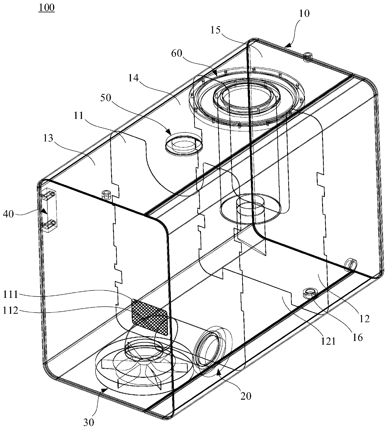
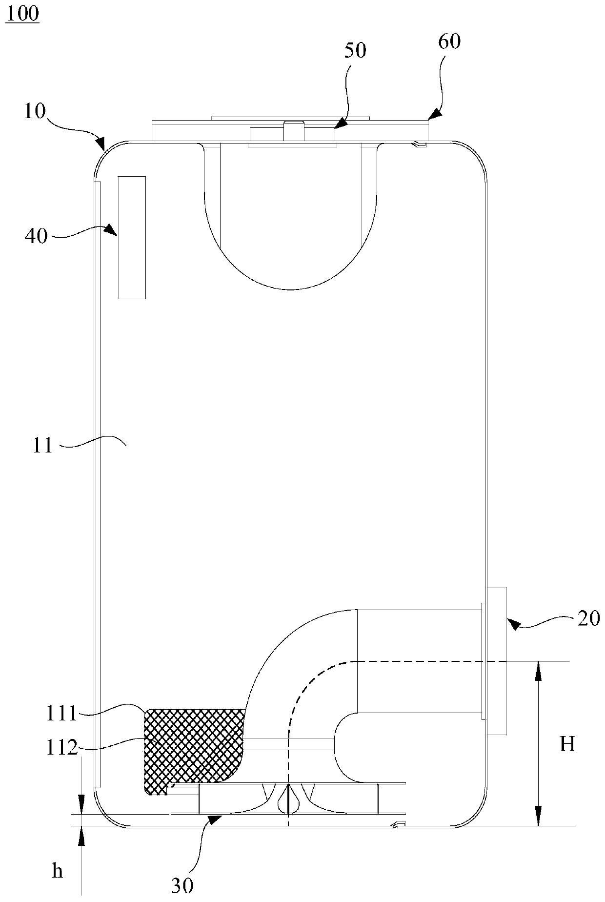
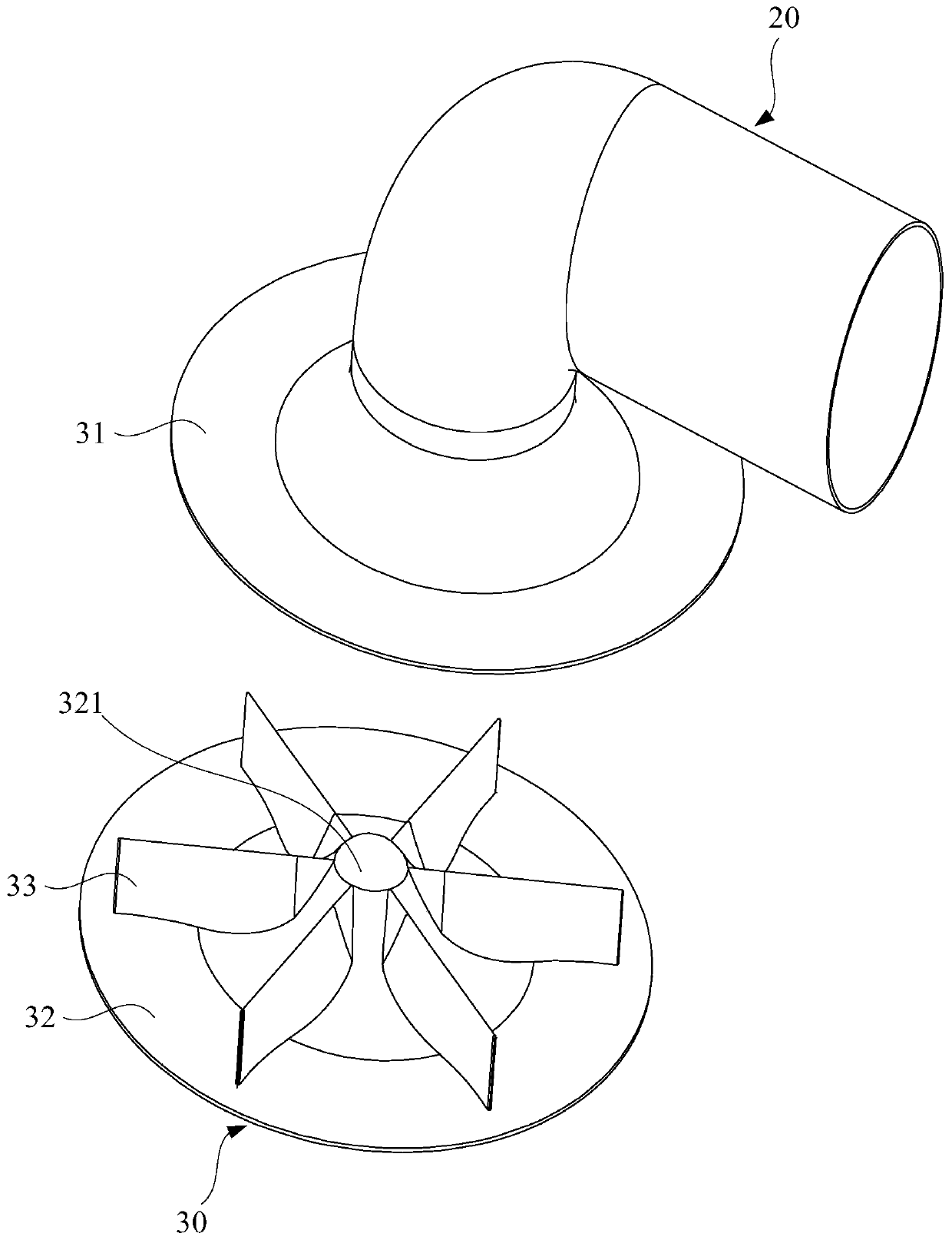
[0030] Please refer to Figure 1 to Figure 3 , the present embodiment provides a hydraulic oil tank 100, which includes a main body 10 of the oil tank, an oil suction pipe 20 and a swirl preventer 30. The main body of the oil tank 10 is a hollow structure with a housing chamber, and the oil suction pipe 20 extends into the housing chamber, and the oil suction pipe 20 The oil suction port of the oil tank is facing the bottom wall of the oil tank main body 10. The swirl preventer 30 includes a top plate 31 and a bottom plate 32 which are opposite and arranged at intervals. The top plate 31 has a circular structure. At one end, the swirl preventer 30 further includes a plurality of deflectors 33 arranged between the top plate 31 and the bottom plate 32 , and a gap is formed between two adjacent deflectors 33 . The hydraulic oil tank 100 can avoid the swirl phenomenon at the oil suction port inside the oil tank, thereby avoiding the cavitation phenomenon of the oil pump.

[0031]...


PUM


Abstract

The invention discloses a hydraulic oil tank and an engineering machine, and relates to the hydraulic technical field. The hydraulic oil tank comprises an oil tank main body, an oil suction pipe and acyclone preventer, wherein the oil tank main body is of a hollow structure with an accommodating cavity, the oil suction pipe extends into the accommodating cavity, an oil suction port of the oil suction pipe faces to the bottom wall of the oil tank main body, the cyclone preventer comprises a top plate and a bottom plate which are arranged oppositely in a spaced mode, the top plate is of a ring-shaped structure, and the top plate is arranged at the end, provided with the oil suction port, of the oil suction pipe in a sleeved mode; the cyclone preventer further comprises a plurality of guideplates arranged between the top plate and the bottom plate, and a gap is formed between every two adjacent guide plates. According to the hydraulic oil tank and the engineering machine, the rotationalflow phenomenon at the oil suction port in the oil tank can be avoided, and therefore the cavitation phenomenon of an oil pump can be avoided.

Description

technical field [0001] The invention relates to the field of hydraulic technology, in particular to a hydraulic oil tank and engineering machinery. Background technique [0002] Most construction machinery is inseparable from the hydraulic system, and the oil pump is the power component of the entire hydraulic system. Once damaged, the entire hydraulic system will be paralyzed. [0003] Cavitation is the most common fault in oil pumps. The main cause of cavitation is that when the oil pump works at the maximum flow rate, the liquid level of the hydraulic oil tank is lower than the minimum standard liquid due to function expansion or hydraulic oil leakage. At this time, swirling flow will be generated at the oil suction port inside the oil tank. Once the liquid level in the middle of the swirling flow is lower than the top of the oil suction pipe, a small amount of air will be sucked in, which will cause cavitation and abnormal noise in the oil pump, and reduce the service li...

Claims


Application Information

Patent Timeline
Patent Type & Authority Applications(China)
IPC IPC(8): F15B1/26F15B19/00F15B21/041F15B21/047
CPCF15B1/26F15B19/00F15B21/041F15B21/047
Inventor 王坤黄孟孙文斌
Owner SANY AUTOMOBILE HOISTING MACHINERY
Learn More