Inductor assembly

A technology of inductors and components, applied in the direction of inductors, fixed inductors, electrical components, etc., to achieve the effect of ensuring impedance and high impedance

Inactive Publication Date: 2020-01-03
江苏龙洋电力设备有限公司
View PDF1 Cites 0 Cited by
  • Summary
  • Abstract
  • Description
  • Claims
  • Application Information

AI Technical Summary

Problems solved by technology

7

Method used


Image

  • Inductor assembly
  • Inductor assembly
  • Inductor assembly

Examples


Embodiment Construction

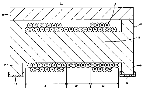
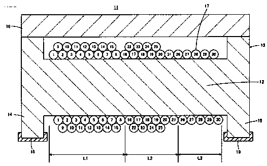
[0034] Such as figure 1 As shown, the inductor component 21 comprises a drum-shaped core 13 having a core portion 12 extending in the longitudinal direction. The drum-shaped core includes a pair of flange portions 14 and 15 provided at respective ends of the core portion 12 . The inductor component 11 includes a plate-shaped core 16 bridging a pair of flange portions 14 and 15 . The drum core 13 and the plate core 16 are made of magnetic materials such as ferrite, and form a closed magnetic circuit.

[0035] The wire 17 is helically wound on the core 12 . The winding form of the wire 17 will be described in detail later. The first and second flange portions 14 and 15 are provided with first and second terminal electrodes 18 and 19, respectively. Although not in figure 1 shown in . Such as figure 1As shown, respective ends of the wire 17 are electrically connected to the first terminal electrode 18 and the second terminal electrode 19 .

[0036] Such as figure 1 As...


PUM


Abstract

The invention discloses an inductor assembly. When the winding density represents the number of turns of wires per unit length in the longitudinal direction of a core part, a plurality of inductor regions having different wire winding densities are arranged in the longitudinal direction of the core part. A low-density inductor region with relatively low winding density is located between first andsecond high-density inductor regions with relatively high winding density.

Description

technical field [0001] The invention relates to the technical field of inductor components, in particular to a wire-wound inductor component with a structure, wherein wires are wound on the core of the core. Background technique [0002] For example, as described in Japanese Unexamined Patent Application Publication No. 2004-363178, a wire wound inductor part has a structure in which a wire is wound on a core portion of a core made of a magnetic material. Also, the inductor component described in Japanese Unexamined Patent Application Publication No. 2004-363178 basically has an inductor for a core. [0003] The equivalent circuit of the wirewound inductor component is in figure 2 shown in . 5. Such as figure 2 shown. Such as Figure 5 As shown, the equivalent circuit of the inductor part has the inductance L provided initially as a basic element and the capacitance C derived from the distributed capacitance (stray capacitance) etc. generated between the windings, and ...

Claims


Application Information

Patent Timeline
IPC IPC(8): H01F17/04H01F27/28
CPCH01F17/04H01F17/045H01F27/2823
Inventor 范宝龙
Owner 江苏龙洋电力设备有限公司
Why Eureka
Try Eureka