Device for sticking magnetic steel in casing

A technology of magnetic steel and casing, which is applied in the field of sticky magnetic steel devices in the casing, which can solve the problems of poor motor quality and low assembly precision of magnetic steel, and achieve the effect of avoiding magnetic steel deviation and precise assembly position

Pending Publication Date: 2020-01-03
HENGDIAN GRP INNUOVO ELECTRIC
View PDF0 Cites 5 Cited by
  • Summary
  • Abstract
  • Description
  • Claims
  • Application Information

AI Technical Summary

Problems solved by technology

[0003] Some motors have a certain angle requirement between the casing and the magnetic steel. There is usually a process hole on the casing of this type of motor (as a drainage hole, or as a lubricating oil injection hole), and the angle between the process hole and the magnetic steel needs to be determined. Position, now draw marks on the inner wall of the magnetic steel with a pen, and then let the edge of the magnetic steel stick to the pen mark, the assembly accuracy of the magnetic steel is low, and the quality of the motor is poor

Method used


Image

  • Device for sticking magnetic steel in casing
  • Device for sticking magnetic steel in casing
  • Device for sticking magnetic steel in casing

Examples


Embodiment Construction

[0022] The present invention will be further described below according to the accompanying drawings and specific embodiments.

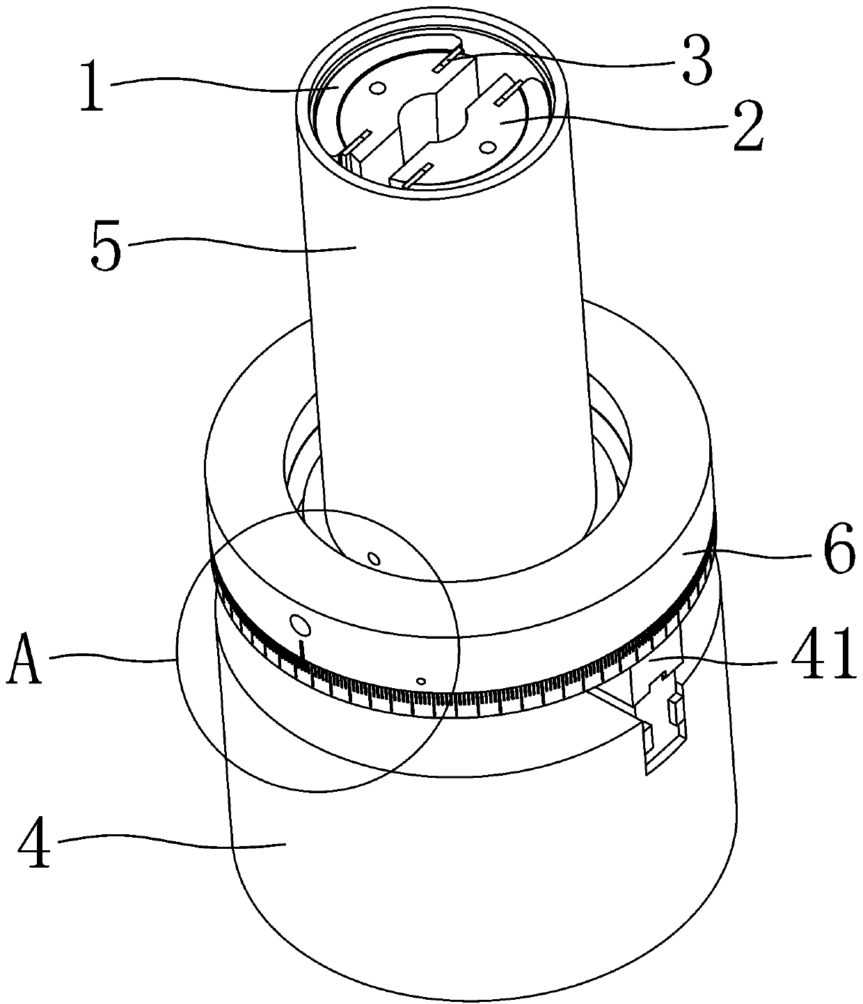
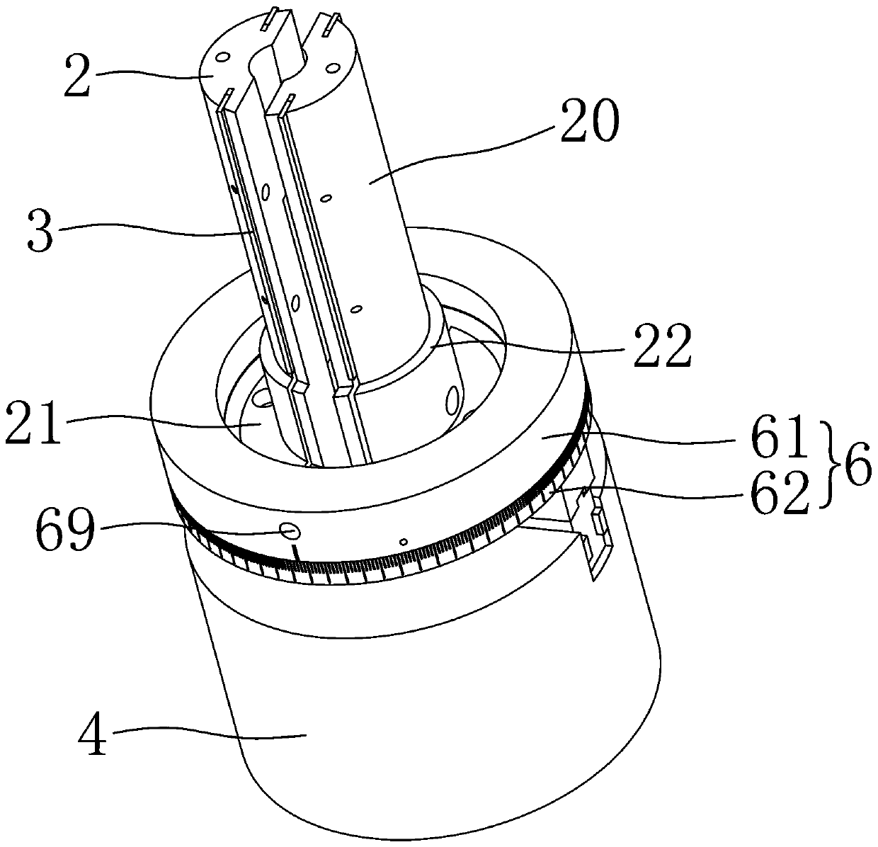
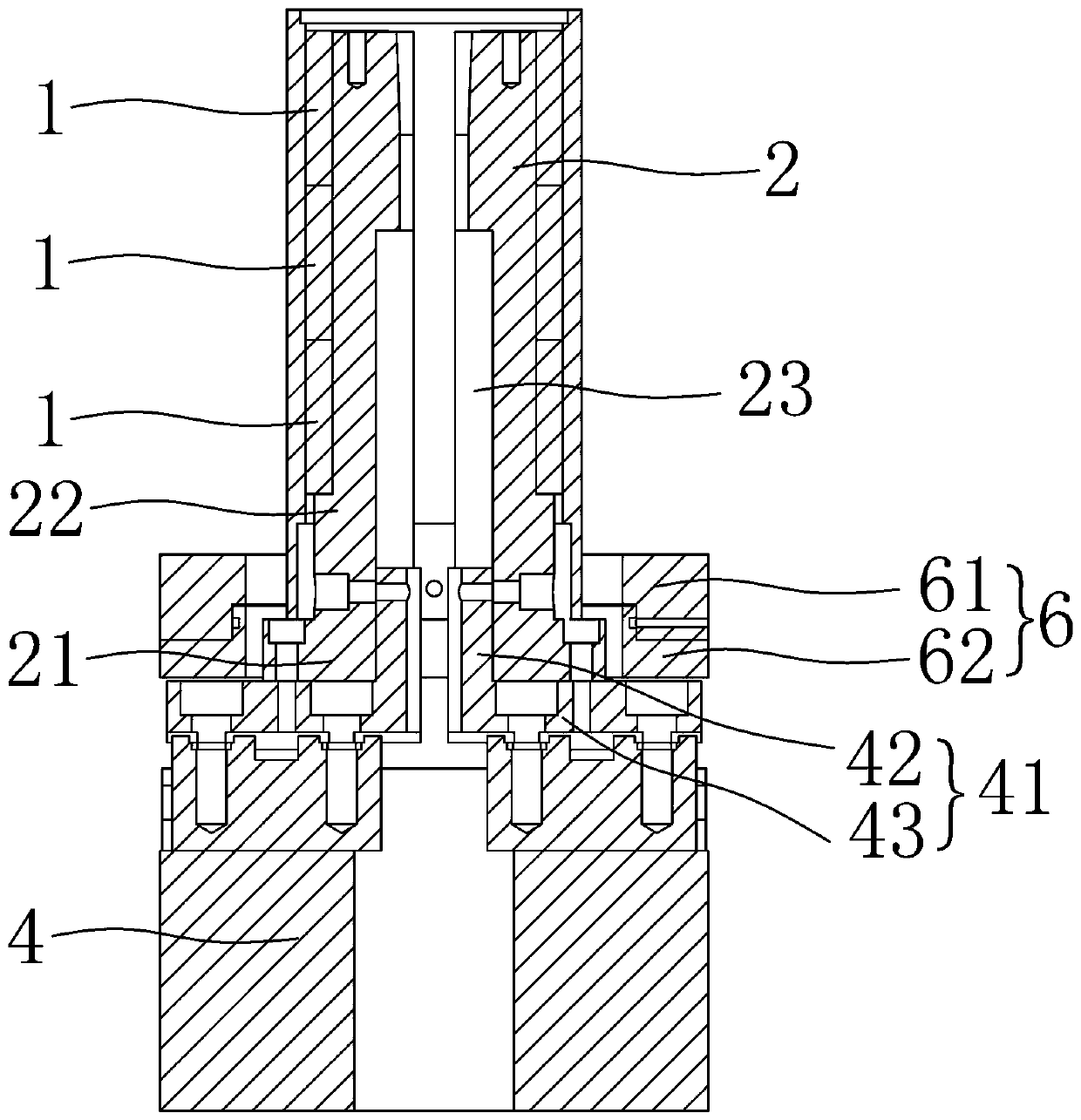
[0023] Depend on Figure 1 to Figure 5 As shown, a magnetic steel sticking device in a casing of the present invention includes a plurality of movable blocks 2 arranged at uniform intervals in a ring, the movable blocks 2 are fixed on the output end of the driving mechanism 4, and the casing 5 is sleeved on the The movable block is circumferentially outside and supported on the first supporting platform 21, and the movable block 2 moves to the casing 5 inner wall side under the effect of the driving mechanism 4, and the movable block 2 lower ends all extend to the circumferentially outside to form a magnetic support. The second support platform 22 of steel 1, the distance between the second support platform 22 circumferential outer edge and the movable block 2 circumferential outer walls is less than the thickness of the magnetic steel 1, and each mov...


PUM


Abstract

The invention aims to provide a device for sticking a magnetic steel in a casing, which can prevent the magnetic steel from deviating so as to enable the assembly position of the magnetic steel to bemore accurate. In order to achieve the purpose, the invention adopts the following technical scheme: the auxiliary device for sticking a magnetic steel in a casing comprises a plurality of movable blocks; the plurality of movable blocks are annularly arranged at intervals; the movable block is fixed at the output end of a driving mechanism; the casing is arranged on the circumferential outer sideof the movable block in a sleeving mode and supported on a first supporting table; the movable blocks move towards the inner wall side of the casing under the action of the driving mechanism; the lower ends of the movable blocks extend outwards in the circumferential direction to form second supporting tables used for supporting the magnetic steel; the distance between the circumferential outer edge of the second supporting table and the circumferential outer walls of the movable block is smaller than the thickness of the magnetic steel; two check blocks are arranged on the circumferential outer wall of each movable block; the movable blocks are located on the upper side of the second supporting table, and the shape of the outer wall, located between the two check blocks, of each movable block is the same as that of the inner wall of the magnetic steel.

Description

technical field [0001] The invention relates to a magnetic steel sticking device in a casing. Background technique [0002] During the assembly of the motor, it is necessary to fix the magnetic steel on the inner wall of the casing. The magnetic steel is tile-shaped and fixed on the inner wall of the casing by glue. Due to the interaction between the magnets, the magnets will deviate from the set position, so that the quality of the motor will be deteriorated. [0003] Some motors have a certain angle requirement between the casing and the magnetic steel. There is usually a process hole on the casing of this type of motor (as a drainage hole, or as a lubricating oil injection hole), and the angle between the process hole and the magnetic steel needs to be determined. The position is now drawn with a pen on the inner wall of the magnetic steel, and then the edge of the magnetic steel is attached to the pen mark. The assembly accuracy of the magnetic steel is low, and the qua...

Claims


Application Information

Patent Timeline
Patent Type & Authority Applications(China)
IPC IPC(8): H02K15/03
CPCH02K15/03
Inventor 汪宏俊
Owner HENGDIAN GRP INNUOVO ELECTRIC
Why Eureka
Try Eureka