Riveting pressure tool

A tooling and riveting technology, applied in forming tools, manufacturing tools, metal processing equipment, etc., can solve problems such as high safety risks, unsightly appearance of parts, and high requirements for operators, so as to improve the pass rate, reduce weight, and facilitate processing Effect

Pending Publication Date: 2020-01-07
ZHEJIANG FEIJIAN IND & TRADE
View PDF0 Cites 0 Cited by
  • Summary
  • Abstract
  • Description
  • Claims
  • Application Information

AI Technical Summary

Problems solved by technology

[0003] The present invention aims at the parts in the prior art that manually connect and fasten the sheet metal parts with other parts. The rear tooling cannot be automatically reset

Method used


Image

  • Riveting pressure tool
  • Riveting pressure tool
  • Riveting pressure tool

Examples


Embodiment 1

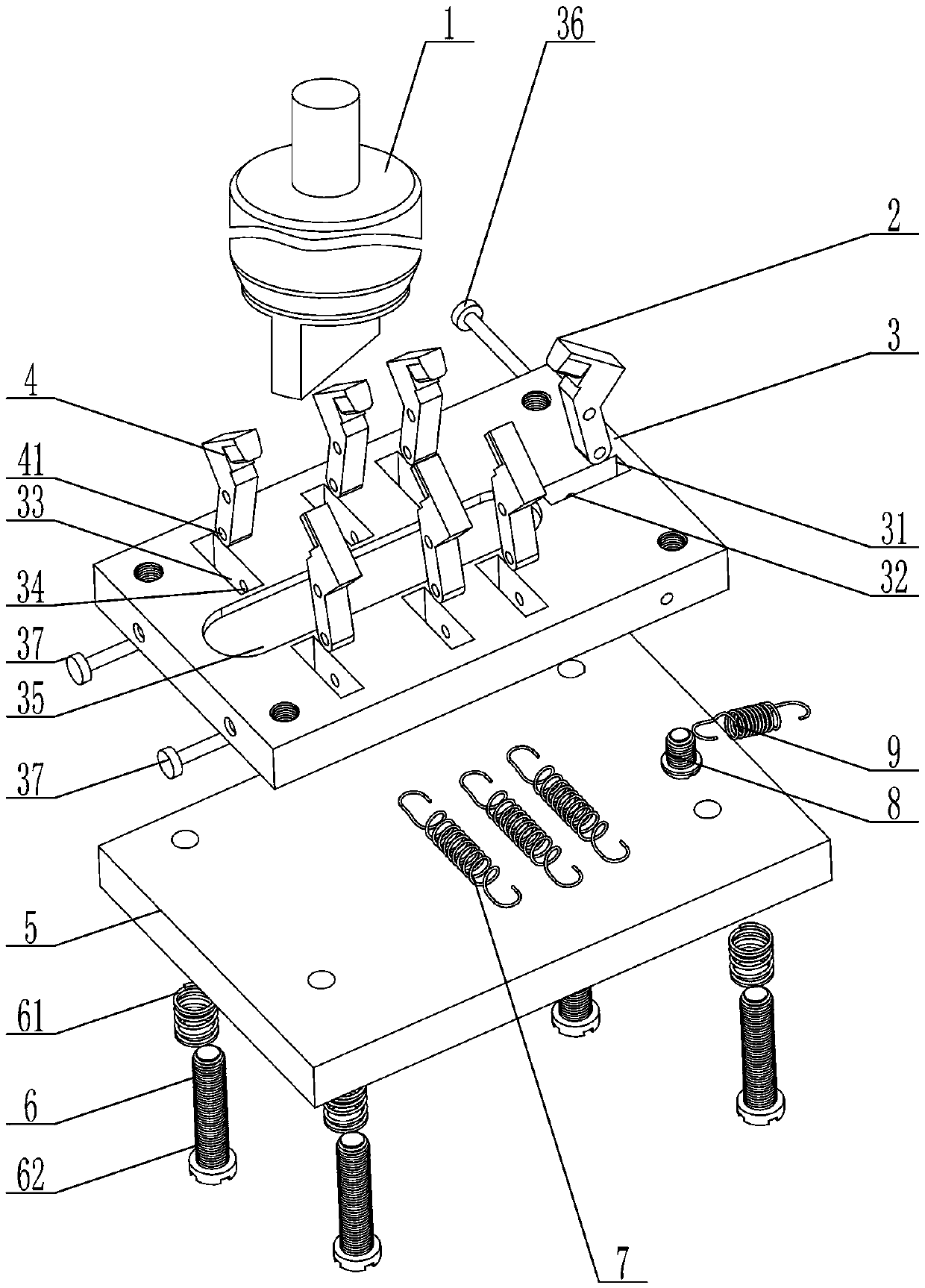
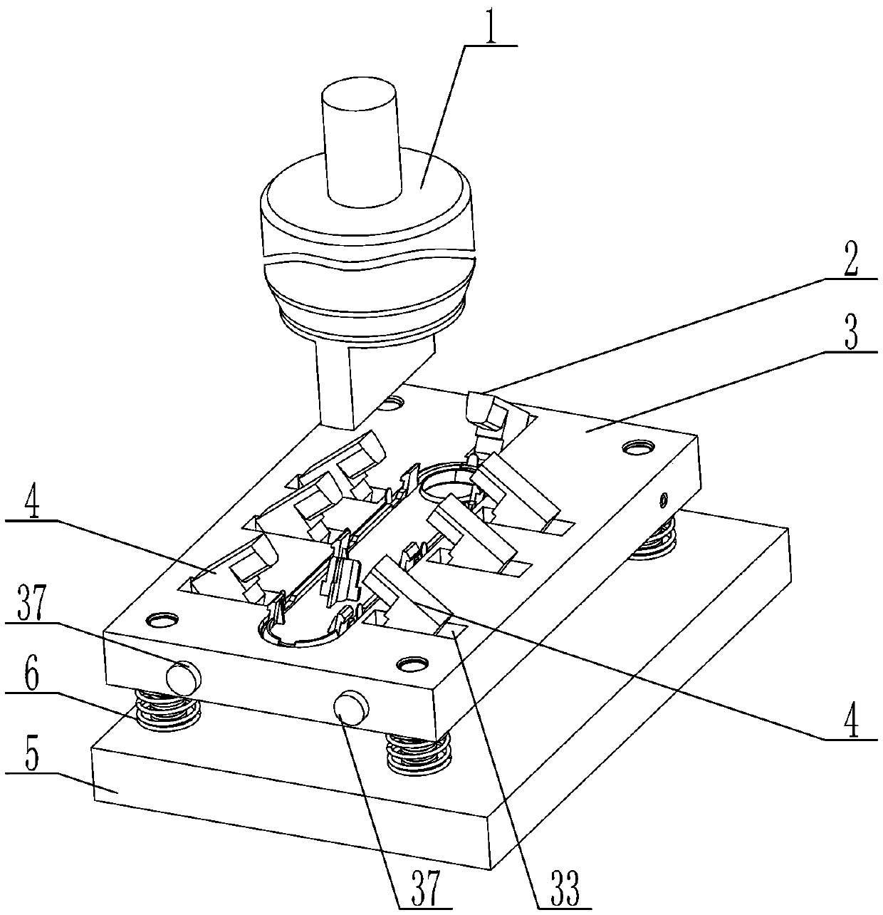
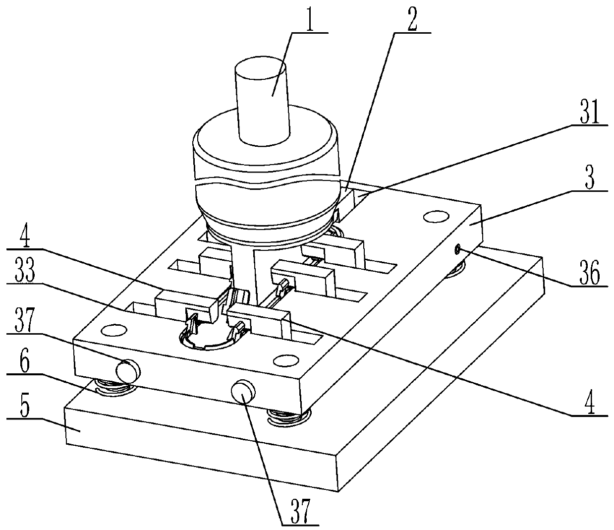
[0035] Such as Figure 1 to Figure 8 As shown, a riveting tooling includes an upper mold 1, a first pressure block 2, a lower mold 3, a fixed plate 5, and a guide and positioning member 6, and the lower mold 3 is provided with a first fixed shaft 36, and the The upper mold 1 fits with the lower mold 3 and drives the lower mold 3 to move downward, the guide positioning member 6 passes through the fixed plate 5 and is connected with the lower mold 3, and also includes Extension spring fixed shaft 8, the first extension spring 9, the first extension spring hole 22 is arranged on the first pressure block 2, the extension spring fixed shaft 8 is connected with the lower mold 3, the described One end of the first extension spring 9 is connected with the extension spring fixed shaft 8, and the other end of the first extension spring 9 is connected with the first extension spring hole 22 on the first pressure block 2, and the The bottom of the first pressing block 2 is in contact wit...


PUM


Abstract

The invention discloses a riveting pressure tool. The riveting pressure tool comprises an upper die, a first pressure block, a lower die, a fixing plate and a guide positioning part, the lower die isprovided with a first fixing shaft, and the upper die is matched with the lower die and drives the lower die to move downwards; the guide positioning part penetrates through the fixing plate and is connected with the lower die, the riveting pressure tool further comprises a tension spring fixing shaft and a first tension spring, and the first pressure block is provided with a first tension springhole; the tension spring fixing shaft is connected with the lower die, one end of the first tension spring is connected with the tension spring fixing shaft, and the other end of the first tension spring is connected with the first tension spring hole in the first pressure block; the bottom of the first pressure block is in contact with the fixing plate, and the first pressure block is rotatably connected to the lower die through the first fixing shaft. The riveting pressure tool can be automatically reset after riveting pressure is completed, the safety level and processing efficiency are improved, and the operation difficulty is lowered so that a common operator can also be qualified for riveting pressure work.

Description

technical field [0001] The invention relates to the field of tooling, in particular to a riveting tooling. Background technique [0002] In the prior art, when a sheet metal part needs to be connected and fastened with other parts, methods such as welding, threaded connection, bonding, crimping, and riveting are usually used, because the riveting connection and fastening method is easy to operate , low cost, and easy disassembly and maintenance between subsequent parts, so it is favored by the majority of users. In the prior art, most users usually manually connect and fasten the sheet metal parts with other parts. The appearance of the parts that are manually connected and fastened is not beautiful, and the connection relationship between parts is difficult to meet the requirements. Some users also use simple tooling for connection and fixation, but the simple tooling cannot be automatically reset after the riveting is completed and needs to be manually reset by the user, ...

Claims


Application Information

Patent Timeline
IPC IPC(8): B21D39/00B21D37/10B21D37/12
CPCB21D37/10B21D37/12B21D39/00
Inventor 林勇史马圣饶胜夏飞剑
Owner ZHEJIANG FEIJIAN IND & TRADE
Why Eureka
Try Eureka