
Adhesive sticker die-cutting machine with constant temperature waste discharge function

A technology of constant temperature and rubber mold, which is applied in metal processing and other directions, can solve the problem of low reliability of die-cutting waste discharge, and achieve the effect of improving waste discharge efficiency, improving waste discharge reliability, and facilitating waste discharge

Inactive Publication Date: 2020-01-07
柏志强 +1
View PDF5 Cites 1 Cited by
  • Summary
  • Abstract
  • Description
  • Claims
  • Application Information

AI Technical Summary

Problems solved by technology

[0003] Aiming at the above-mentioned prior art, the present invention provides a self-adhesive die-cutting machine with constant temperature waste discharge. The die-cut waste discharge can not be affected by the temperature of the working environment. The waste discharge unit is mainly used in the traction roller and the resistance A constant temperature control device is installed between the pressing rollers so that the material to be discharged has a constant temperature when it enters the stage of die-cutting and waste discharge, so that the adhesiveness of the adhesive is constant, and it is easy to peel and discharge waste, which solves the problem of the reliability of die-cut waste discharge in the prior art Low problem, the corresponding increase in production efficiency

Method used


Image

  • Adhesive sticker die-cutting machine with constant temperature waste discharge function
  • Adhesive sticker die-cutting machine with constant temperature waste discharge function
  • Adhesive sticker die-cutting machine with constant temperature waste discharge function

Examples


Embodiment Construction

[0018] The technical solution of the present invention will be further described in detail below in conjunction with the accompanying drawings and specific embodiments, and the described specific embodiments are only for explaining the present invention, and are not intended to limit the present invention.

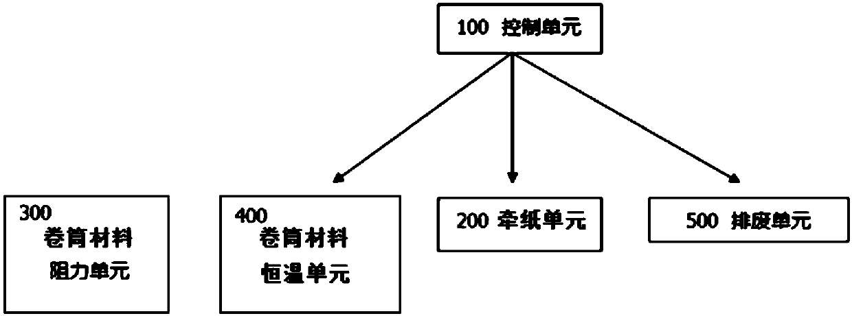
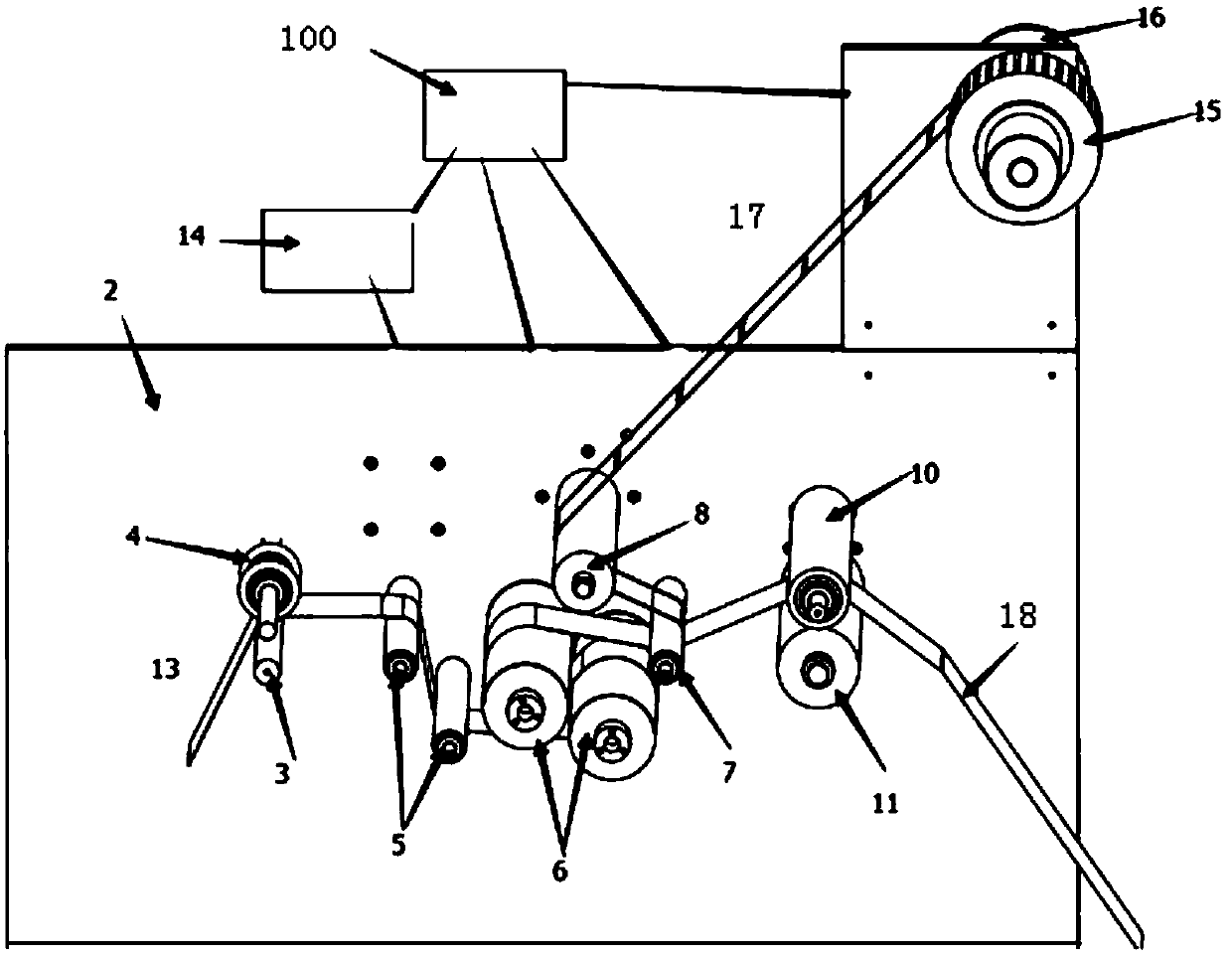
[0019] A self-adhesive die-cutting machine with constant temperature waste discharge proposed by the present invention includes a support plate 2 on which a paper pulling unit 200, a roll material resistance unit 300 and a waste discharge unit 500 are installed. Both the paper pulling unit 200 and the waste discharge unit 500 are connected with a control unit 100; figure 1 and image 3 shown.

[0020] Such as image 3 and Figure 4 As shown, the paper pulling unit 200 in the present invention includes a traction motor 12 controlled by the control unit 100, a traction roller 11 driven by the traction motor 12, and a traction pinch roller 10 matched with the traction rol...


PUM


Abstract

The invention discloses an adhesive sticker die-cutting machine with the constant temperature waste discharge function. The adhesive sticker die-cutting machine with the constant temperature waste discharge function comprises a supporting plate. A paper traction unit, a rolled material resistance unit and a waste discharge unit are installed on the supporting plate. The paper traction unit and thewaste discharge unit are both connected with a control unit. A rolled material constant temperature unit is arranged on the supporting plate and located in front of the position where the adhesive sticker rolled material enters the waste discharge unit. The rolled material constant temperature unit comprises a temperature sensor, a pair of front guide rollers and a heating device, for instance, apair of heating rollers as the heating device, wherein the temperature sensor and the heating device are both connected with the control unit. According to the adhesive sticker die-cutting machine with the constant temperature waste discharge function, by arranging the rolled material constant temperature unit between a traction roller and a resistance press roll, when to-be-discharged waste enters a die-cutting waste discharge stage, the to-be-discharged waste has a constant temperature, so that the adhesiveness of adhesive is constant, and stripping and waste discharge are easy; and the problem that in the prior art, die-cutting waste discharge is low in reliability is solved, and the production efficiency is improved correspondingly.

Description

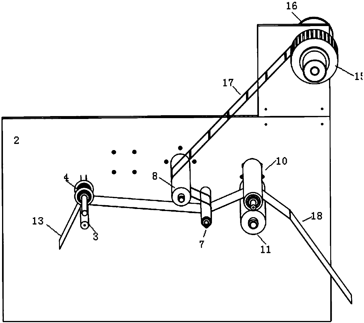
technical field [0001] The invention relates to a die-cutting machine, in particular to a self-adhesive die-cutting machine. Background technique [0002] In the manufacturing process of roll stickers and similar material products, die-cutting machines are usually used, and die-cutting waste needs to be excluded during the die-cutting process. However, the basic structure of existing sticker die-cutting machines is as follows: figure 2 As shown, it includes a paper pulling unit 200 installed on the support plate 2, a roll material resistance unit 300 and a waste discharge unit 500. The self-adhesive roll material 13 passes between the resistance roller 3 and the resistance pressure roller 4 in turn from the unwinding device and winds around After passing the waste discharge guide roller 7, the waste material layer is separated from the self-adhesive roll material 13, the waste material 18 is wound on the waste material drum 15 after passing through the waste discharge roller...

Claims


Application Information

Patent Timeline
Patent Type & Authority Applications(China)
IPC IPC(8): B26D7/10B26F1/38
CPCB26D7/10B26F1/38
Inventor 柏志强韩蓓
Owner 柏志强
Learn More