A square head bolt marking device

A technology of square head bolt and marking unit, which is applied in printing devices, typewriters, transportation and packaging, etc., can solve the problems of high production cost and low production efficiency, and achieve the goal of improving production efficiency, ensuring orientation and avoiding position deviation. Effect

Active Publication Date: 2021-04-13
海盐巨龙标准件有限公司
View PDF6 Cites 0 Cited by
  • Summary
  • Abstract
  • Description
  • Claims
  • Application Information

AI Technical Summary

Problems solved by technology

However, before the existing marking machine marks the bolts, it is necessary to manually place the lag bolts on the marking machine, which leads to high production costs and low production efficiency.

Method used


Image

  • A square head bolt marking device
  • A square head bolt marking device

Examples


Embodiment Construction

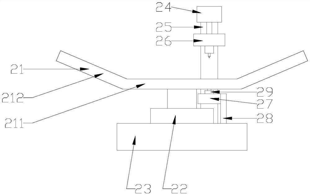
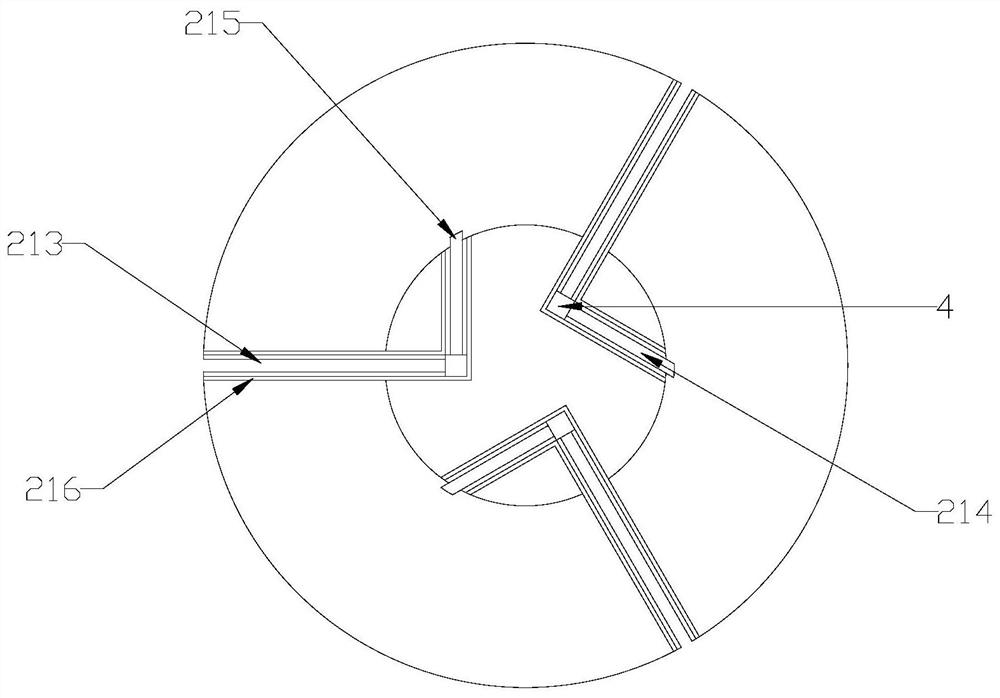
[0013] refer to figure 1 with figure 2 , a lag bolt marking device of the present invention includes a turntable 21, a motor 22, a base 23, a marking unit and an ejection unit, the motor 22 is fixed on the base 23 and drives the turntable 21 to rotate through a rotating shaft, and the turntable 21 includes an inner plate 211 and a side wing 212 that is located at the edge of the inner plate 211 and is turned over to the top in a ring shape. The turntable 21 is provided with several first passages 213 extending from the outer edge of the side wing 212 to the inner plate 211. The connection between the inner plate 211 and the side wings 212 is provided with several outlets 215, and the first channel 213 is located between one end of the inner plate 211 and the outlet 215, and a second channel 214 is provided between the first channel 213 and the second channel 214. An electromagnet is provided at the junction of the first channel 213 and the second channel 214, and a side plat...


PUM


Abstract

The invention discloses a lag bolt marking device, which includes a turntable, a motor, a base, a marking unit and an ejection unit. The motor is fixed on the base and drives the turntable to rotate through a rotating shaft. The turntable includes an inner plate and a The edge of the inner plate is ring-shaped and folded to the top. The turntable is provided with several first channels extending from the outer edge of the side wing to the inner plate. The connection between the inner plate and the side wing is provided with several outlets. The first channel is located between one end of the inner plate and the outlet, and a second channel is provided. The connection between the first channel and the second channel is provided with an electromagnet, and the sides of the first channel and the second channel are provided with A side plate that restricts the rotation of the screw head of the lag bolt, the marking head of the marking unit is located above the intersection of one of the first channels and the second channel, and the top block of the ejection unit is located in the other first channel The bottom and rear of the intersection with the second channel can automatically complete the feeding and discharging of bolts, effectively improving production efficiency.

Description

【Technical field】 [0001] The invention relates to the technical field of bolts, in particular to the technical field of a lag bolt marking device. 【Background technique】 [0002] During the production and processing of square head bolts, the manufacturer's mark needs to be marked to identify the manufacturer. In addition, the material, performance level and strength of the bolt need to be marked. However, before the existing marking machine marks the bolts, it is necessary to manually place the lag bolts on the marking machine, which has high production costs and low production efficiency. 【Content of invention】 [0003] The purpose of the present invention is to solve the problems in the prior art, and propose a lag bolt marking device, which can automatically complete the feeding and discharging of bolts, and effectively improve production efficiency. [0004] In order to achieve the above object, the present invention proposes a lag bolt marking device, including a tur...

Claims


Application Information

Patent Timeline
Patent Type & Authority Patents(China)
IPC IPC(8): B65G47/24B65G47/82B65G47/92B41J3/407B41J11/00
CPCB41J3/407B41J11/00B65G47/24B65G47/82B65G47/92
Inventor 时燕军
Owner 海盐巨龙标准件有限公司
Why Eureka
Try Eureka