Automatic rotation anti-blocking bottom lattice fence

An automatic rotation and anti-blocking technology, applied in the field of preventing the bottom grille from being blocked, can solve the problems of affecting the water intake effect and blocking the bottom grille, so as to avoid blockage and reduce the project cost.

Inactive Publication Date: 2020-01-07
SICHUAN UNIV
View PDF7 Cites 3 Cited by
  • Summary
  • Abstract
  • Description
  • Claims
  • Application Information

AI Technical Summary

Problems solved by technology

But this kind of traditional bottom grid, there are always pebbles and other sundries of different sizes and shapes that will be stuck on the upper part of the grid, and gradually accumulate more and more, eventually causing the bottom grid to be completely blocked. Therefore, it is necessary to clean the blockage frequently during use, otherwise it will affect the water intake effect
[0003] Therefore, it is necessary to develop a bottom grid that can automatically discharge sewage to prevent it from being blocked by debris such as pebbles and affecting the water intake effect.

Method used


Image

  • Automatic rotation anti-blocking bottom lattice fence
  • Automatic rotation anti-blocking bottom lattice fence
  • Automatic rotation anti-blocking bottom lattice fence

Examples


Embodiment 1

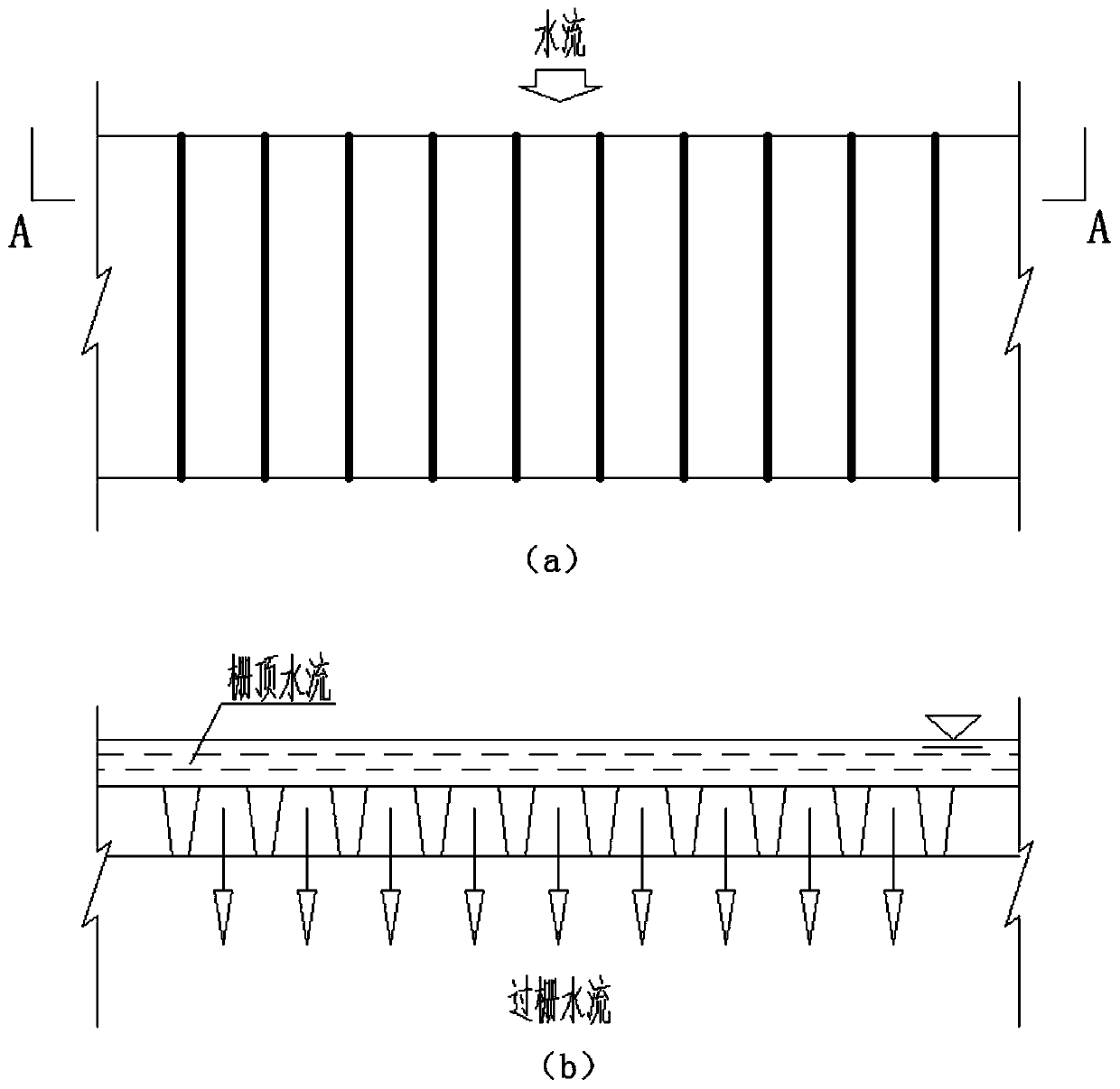
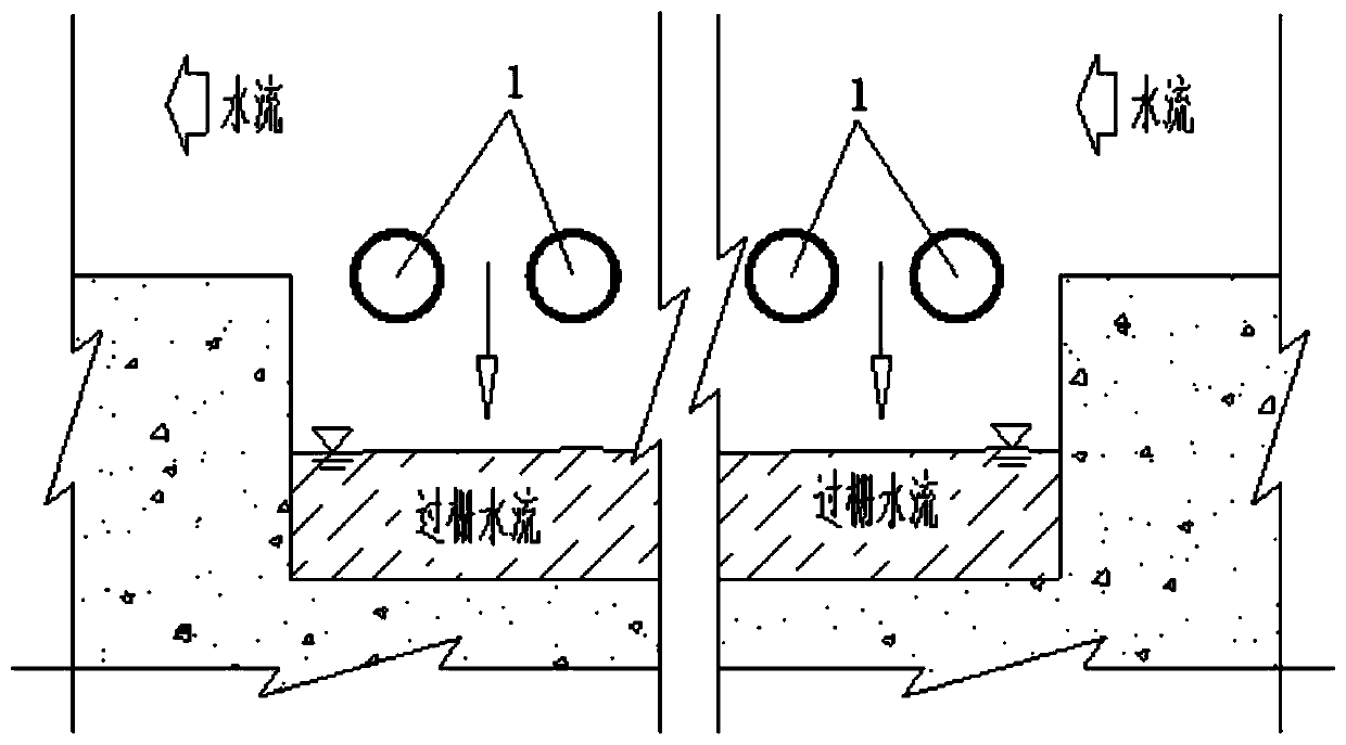
[0026] The automatically rotating anti-clogging bottom grid fence provided by this embodiment, such as figure 2 As shown, a number of grids 1 perpendicular to the water flow direction are arranged at equal intervals along the water flow direction at the top of the intake of the water intake corridor. Both ends of the grid are rotatably installed in the two side walls of the water intake corridor through bearings 2. The ends are respectively installed with a water flow impact drive mechanism.

[0027] Such as Figure 3 to Figure 5 As shown, the grid bars used in this embodiment have a cylindrical structure, and the interval between two adjacent grid bars is 0.05-0.2 m.

[0028] Such as Figure 5 As shown, the bearing used in this embodiment is a ball bearing, the ball bearing is fixed in the concrete walls on both sides of the water intake corridor, and the ball bearing is in interference fit with the grid.

[0029] Such as Figure 4 As shown, the water flow impact driving mechanism...

Embodiment 2

[0033] The self-rotating anti-clogging bottom grid fence provided in this embodiment is based on the bottom grid fence provided in Embodiment 1, and is a further improvement on the water flow impact driving mechanism.

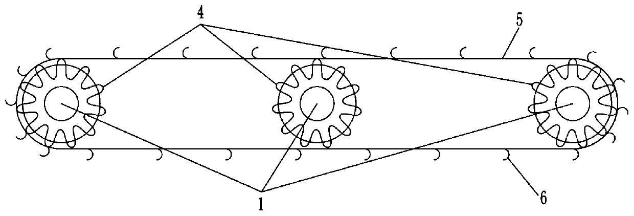
[0034] The water flow impact driving mechanism provided in this embodiment, such as Figure 7 As shown, it includes pulleys 7 fixedly installed at both ends of the grid and a transmission belt 8 matched with all pulleys. The belt wheel 7 is a groove structure wheel, and the width of the groove matches the width of the transmission belt. A number of impact buckets for bearing the impact of water flow are evenly arranged on the outer side of the transmission belt in the circumferential direction. The impact bucket has a cone-shaped bucket structure. The interval between two adjacent impact buckets is 0.1-0.5m.

[0035] The anti-blocking principle of the automatically rotating anti-blocking bottom grid fence provided in this embodiment is the same as that in Embodime...


PUM


Abstract

The invention discloses an automatic rotation anti-blocking bottom lattice fence. A plurality of fence strips vertical to the waterflow direction are distributed on the top of a water taking gallery water inlet in the waterflow direction; the two ends of the fence strips are rotationally arranged in the two side wall surfaces of a water taking gallery through bearings; a waterflow impact driving mechanism is arranged on the fence strips; the fence strips form a conveying fence through being driven by the waterflow impact driving mechanism; and sundries attached onto the fence strips are conveyed to a downstream position. The automatic rotation anti-blocking bottom lattice fence provided by the invention has the advantages that the plurality of fence strips vertical to the waterflow direction are uniformly distributed in the waterflow direction; the fence strips are driven to rotate by using the waterflow impact driving mechanism; the sundries such as pebbles positioned on the bottom lattice fence rotate along with the fence strips, and are then conveyed to the downstream position, so that the automatic pollution discharge of the bottom lattice fence is realized; and the blockage isavoided.

Description

Technical field [0001] The invention belongs to the technical field of water conservancy engineering, and relates to a bottom grid fence used in mountain rivers, in particular to a technology that uses water flow energy to drive the bottom grid fence to automatically rotate to prevent the bottom grid fence from being blocked. Background technique [0002] In traditional water conservancy and hydropower projects, the bottom grid fence dam water intake corridor is used for water intake in mountainous rivers, which includes bottom grid fence and water intake corridor. The bottom grid fence is installed on the top of the inlet of the water intake corridor. The traditional bottom grid fence is a fixed arrangement of several fences along the flow direction (such as figure 1 (a) Shown). In order to prevent pebbles and other debris from blocking between the bars, the bars are generally designed to be large and small to ensure that the pebbles and other debris that can pass through the u...

Claims


Application Information

Patent Timeline
Patent Type & Authority Applications(China)
IPC IPC(8): E02B5/08
CPCE02B5/085
Inventor 邓军张法星田忠卫望汝刘文刘善均许唯临王韦
Owner SICHUAN UNIV
Why Eureka
Try Eureka