Soil sampling device for metal detection

A soil sampling and metal detection technology, applied in sampling devices and other directions, can solve the problems of inability to meet batch sampling, cumbersome operations, and low soil sampling efficiency.

Active Publication Date: 2020-07-07
JIANGXI NORMAL UNIV
View PDF5 Cites 0 Cited by
  • Summary
  • Abstract
  • Description
  • Claims
  • Application Information

AI Technical Summary

Problems solved by technology

[0002] When metal detection is carried out in soil, it is necessary to sample the soil. In order to fully understand the distribution of metals in the soil, it is necessary to sample the soil at each depth of the soil. The traditional sampling device uses a drill pipe to collect the soil column. Finally, the soil column needs to be pushed out from the drill barrel, and the soil samples at different depths need to be separated manually, which is cumbersome to operate, especially when a large amount of soil sampling is performed on a piece of soil, the soil sampling efficiency is low and cannot meet the needs of batch sampling

Method used


Image

  • Soil sampling device for metal detection
  • Soil sampling device for metal detection
  • Soil sampling device for metal detection

Examples


Embodiment 1

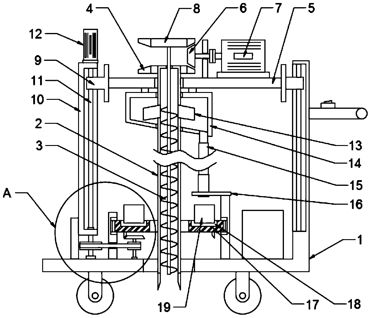
[0022] see Figure 1-4 , in an embodiment of the present invention, a soil sampling device for metal detection includes a cart 1 and a soil fetching mechanism; the soil fetching mechanism includes a drill barrel 2 that can move up and down, and a helical blade roller 3 is arranged in the drill barrel 2, The spiral blade roller 3 lifts the soil sample entering the drill tube 2; the upper end of the drill tube 2 is nested with a lifting frame 5, and the drill tube 2 is rotatably connected to the lifting frame 5 through a bearing; the outer side of the drill tube 2 is sleeved and fixed There is a first bevel gear 4, the first bevel gear 4 is engaged with a drive gear 6, the drive gear 6 is connected to the output shaft of the drive motor 7, the drive motor 7 is electrically connected to the vehicle power supply, and a switch panel is arranged on the cart 1 , to facilitate starting the drive motor 7; the helical blade roller 3 extends to the top of the drill cylinder 2 and is fixe...

Embodiment 2

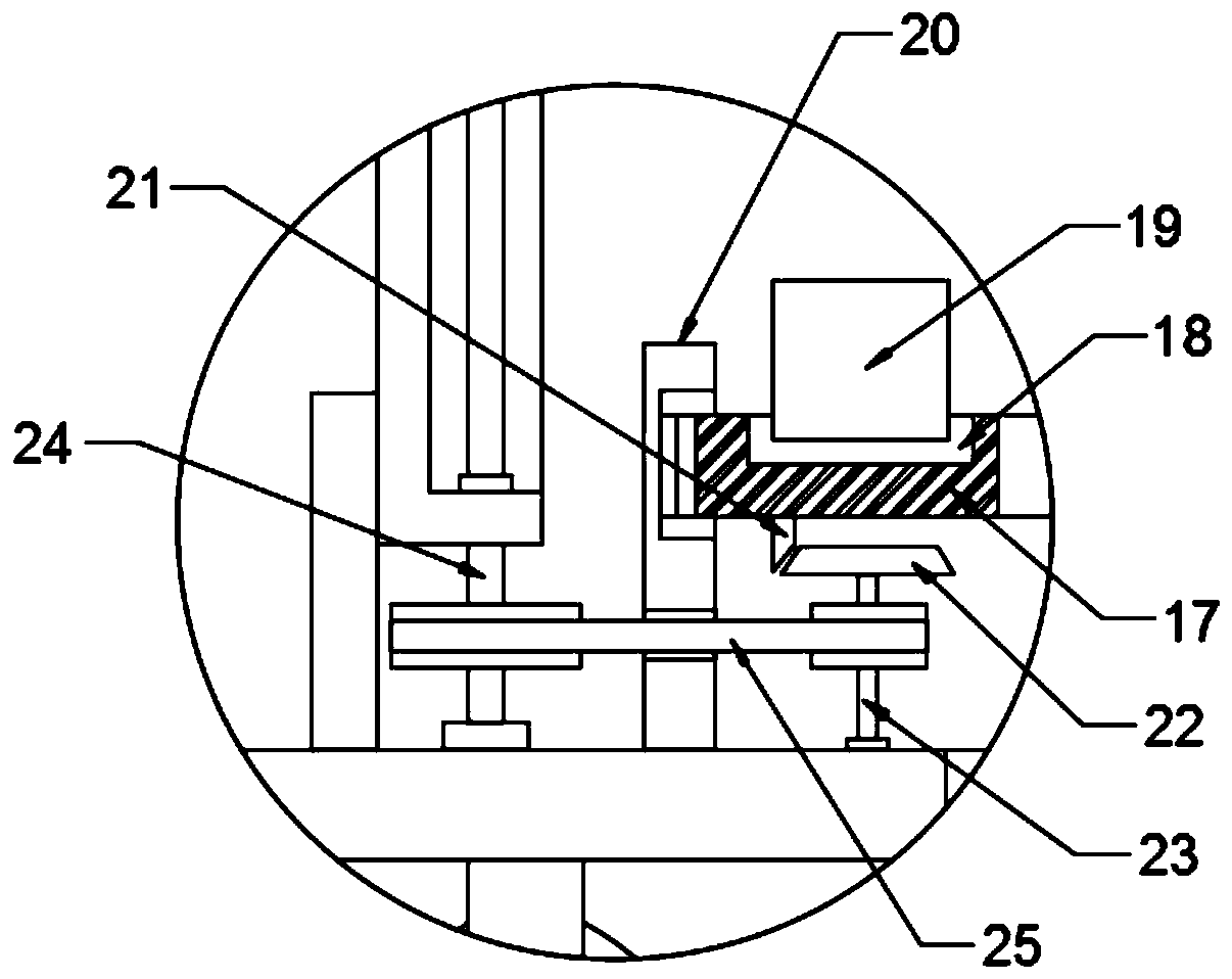
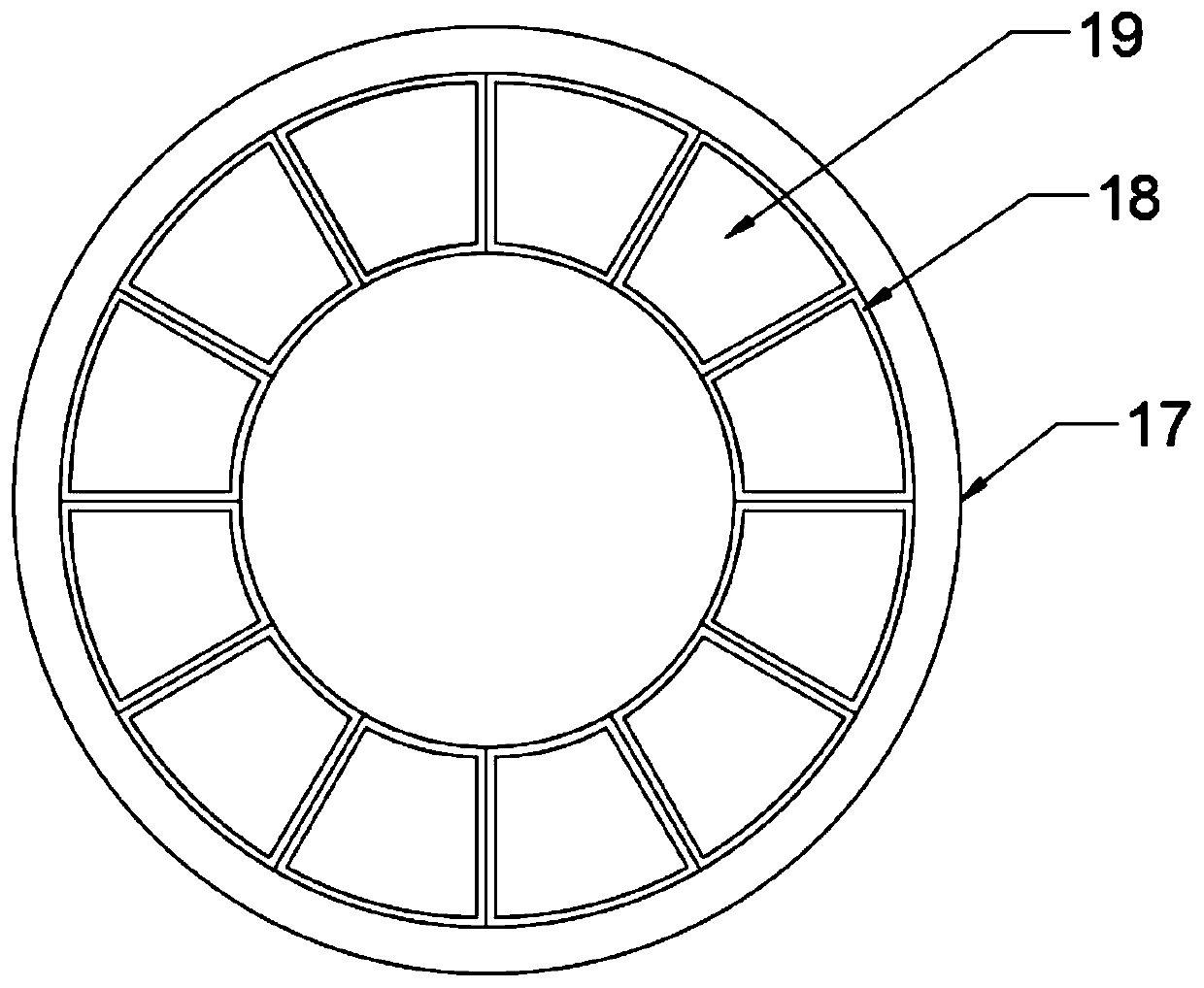
[0026] The difference between this embodiment and Embodiment 1 is that: the outside of the drill barrel 2 is provided with a material receiving mechanism, the material receiving mechanism includes a material receiving barrel 14 sleeved on the outside of the drill barrel 2, and the material receiving barrel 14 is fixedly connected with the lifting frame 5 And it is rotatably connected with the drill barrel 2; the lower end of the receiving barrel 14 is connected with a feeding pipe 15, and the feeding pipe 15 is a telescoping tube; the lower part of the feeding pipe 15 is provided with a bearing plate 17, and the bearing plate 17 is An annular disc set on the outside of the drill barrel 2, the bearing disc 17 is rotatably connected with a ring frame 20, and the ring frame 20 is fixedly connected with the trolley 1; the upper end surface of the bearing disc 17 is provided with fan-shaped grooves 18 distributed in a circle and connected end to end , the fan-shaped groove 18 is nes...


PUM


Abstract

The invention discloses a soil sampling device for metal detection, which comprises a cart and a soil-taking mechanism; the soil-taking mechanism comprises a drill tube which moves up and down, and a helical blade roller is arranged inside the drill tube; The material receiving mechanism includes a material receiving cylinder sleeved on the outside of the drill barrel; the lower end of the material receiving cylinder is connected with a feeding tube, and a rotating bearing plate is arranged under the feeding tube; the upper end of the bearing plate is provided with a Fan-shaped slots distributed on the circumference and connected end to end, and sample boxes are nested in the fan-shaped slots. The present invention realizes efficient lifting of soil samples by providing a drill barrel connected with a discharge pipe on the upper part, a spiral blade roller and a lifting mechanism, and facilitates the subsequent collection of soil; The carrying plate and the sample boxes distributed in a circle can fill the soil samples of different depth layers into each sample box in turn, so as to realize the efficient collection of soil samples, which is efficient and practical.

Description

technical field [0001] The invention relates to the field of soil detection equipment, in particular to a soil sampling device for metal detection. Background technique [0002] When metal detection is carried out in soil, it is necessary to sample the soil. In order to fully understand the distribution of metals in the soil, it is necessary to sample the soil at each depth of the soil. The traditional sampling device uses a drill pipe to collect the soil column, so that Finally, the soil column needs to be pushed out from the drill barrel, and the soil samples at different depths need to be separated manually, which is cumbersome to operate, especially when a large amount of soil sampling is performed on an area of ​​soil, the soil sampling efficiency is low and cannot meet the needs of batch sampling . Contents of the invention [0003] The object of the present invention is to provide a soil sampling device for metal detection to solve the problems raised in the above ...

Claims


Application Information

Patent Timeline
Patent Type & Authority Patents(China)
IPC IPC(8): G01N1/08
CPCG01N1/08
Inventor 张华
Owner JIANGXI NORMAL UNIV
Why Eureka
Try Eureka