
Light extending type lifting device and implementation method

A light, hanger technology, applied in the direction of safety devices, transportation and packaging, load hanging components, etc., can solve the problems of fast installation of steel structure rods, low construction efficiency, affecting the progress of the project, etc., to ensure the safety of hoisting and stability, improve installation and construction efficiency, and ensure the effect of stability

Pending Publication Date: 2021-03-09
CHINA MCC17 GRP
View PDF0 Cites 0 Cited by
  • Summary
  • Abstract
  • Description
  • Claims
  • Application Information

AI Technical Summary

Problems solved by technology

[0003] The above operation method has the following problems: first, the construction efficiency is low, and the amount of work that can be completed every day is relatively limited; second, more operators and special equipment are used in the construction process, resulting in a great waste of manpower and material resources; Third, the installation speed of steel structure rods is fast. When multiple teams work at the same time on site, the relatively limited number of tower cranes cannot meet the progress requirements of on-site rod installation, and the long-term uninterrupted occupation of tower cranes makes it impossible to use tower cranes for other types of work on the construction site. Carry out hoisting operations, seriously affecting the progress of the project

Method used


Image

  • Light extending type lifting device and implementation method
  • Light extending type lifting device and implementation method
  • Light extending type lifting device and implementation method

Examples


Embodiment 1

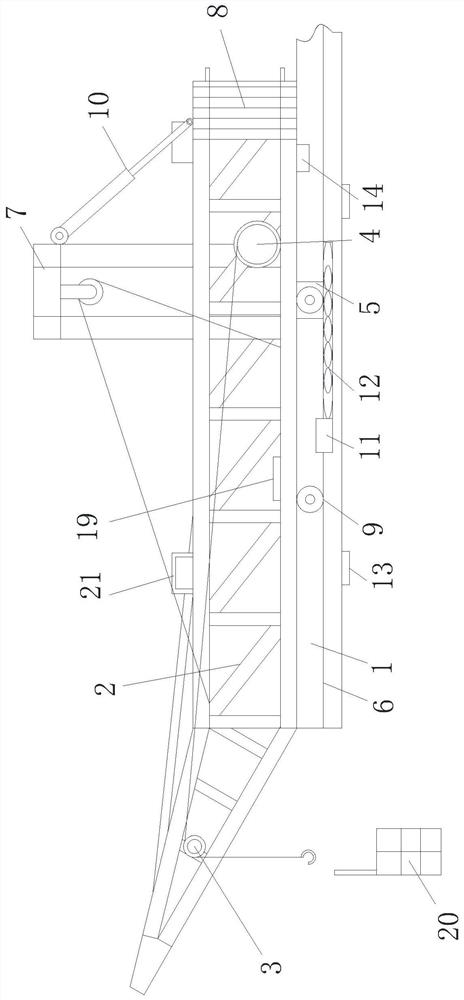
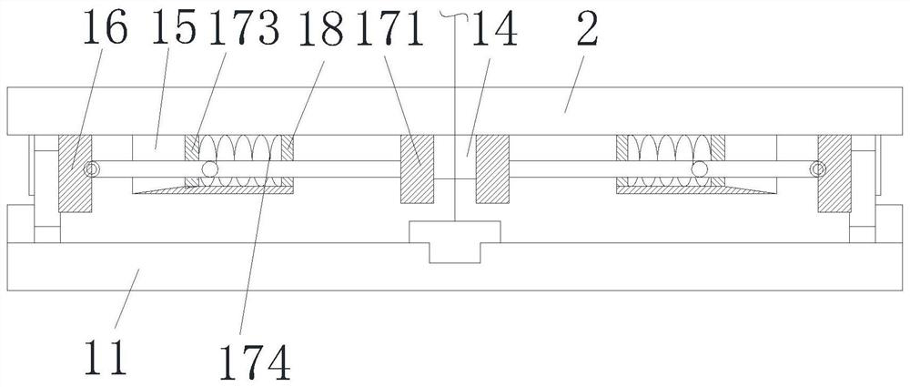
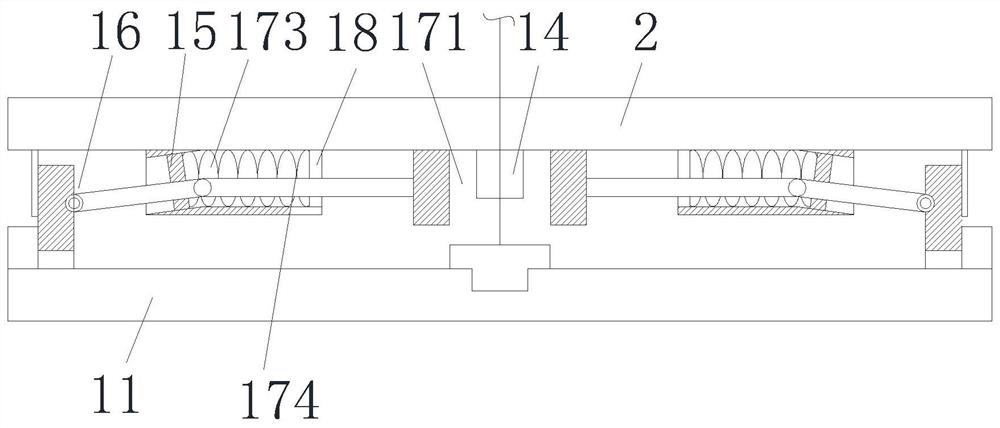
[0031] Such as Figure 1 to Figure 3 As shown, a light-duty protruding lifting device includes a base 1 and a hanger 2 that moves relative to the base 1. The base 1 is provided with a guide rail 6 and a support frame 7, and the hanger 2 is provided with a fixed pulley. 3. Hoist 4, driver 5 and counterweight 8, the fixed pulley 3 is arranged on the front side of the hanger 2, the wire rope on the hoist 4 is connected to a hook through the fixed pulley 3, and the driver The output end of 5 is connected with a transmission member 9 and the transmission member 9 forms a transmission fit with the guide rail 6. The counterweight 8 is arranged at the tail of the hanger 2, and a support member 10 is rotatably installed on the support frame 7. The support The end of the member 10 away from the support frame 7 is rotatably connected to the tail of the hanger 2 , and the support member 10 gradually increases pressure on the rear of the hanger 2 as the hanger 2 moves forward. The driving...

Embodiment approach

[0041] An implementation method of a light-duty protruding lifting device, comprising the following steps:

[0042] Step 1: First, hang the hanger 2 above the base 1 by lifting equipment to ensure that the gear assembly and the rack on the guide rail 6 are meshed and matched, and then rotate the end of the support 10 on the support frame 7 away from the support frame 7 and install it on the At the afterbody of the hanger 2, one end of the connecting rope is fixedly installed on the slide block one 11, and the other end is fixed around the fixed pulley 32 and the front end of the hanger 2, and finally the slide block two 13 is first installed on the base 1 and connected with The hanger 2 is fixedly installed;

[0043] Step 2: Control the driving part 5 through the remote control handle 20 to drive the gear assembly to move forward along the rack, the counterweight 8 moves forward with the hanger 2, and at the same time the support part 10 exerts pressure on the counterweight 8,...


PUM


Abstract

The invention discloses a light extending type lifting device and an implementation method, and belongs to the technical field of lifting devices. The lifting device comprises a base and a hanging bracket moving relative to the base, a guide rail and a supporting frame are arranged on the base, fixed pulleys, a winch, a driving part and a balancing weight are arranged on the hanging bracket, a first fixed pulley is arranged on the front side of the hanging bracket, a steel wire rope on the winch is connected to a lifting hook through the first fixed pulley, a transmission part is connected tothe output end of the driving part and is in transmission fit with the guide rail, the balancing weight is arranged at the tail part of the hanging bracket, a supporting part is arranged on the supporting frame in a rotating mode, the end, away from the supporting frame, of the supporting part is connected to the tail part of the hanging bracket in a rotating mode, and the supporting part gradually increases and applies pressure to the rear part of the hanging bracket along with the forward movement of the hanging bracket. The lifting device has the advantages of being convenient to use, quick, efficient, capable of reducing the consumption of manpower and mechanical machine teams and capable of improving the installation and construction efficiency.

Description

technical field [0001] The invention relates to the technical field of lifting devices, in particular to a light-duty protruding lifting device and an implementation method. Background technique [0002] In local space or steel structure construction, due to the cramped space or dense rods, it is difficult to transport materials from a low place to the working surface. The general method used on the construction site is: when constructing in a local space, the materials are first horizontally transported to the construction elevator , after being vertically transported to the specified height by the construction elevator, the materials are transported horizontally to the construction work surface; when hoisting steel structure rods, tower cranes are generally used for hoisting. [0003] The above operation method has the following problems: first, the construction efficiency is low, and the amount of work that can be completed every day is relatively limited; second, more op...

Claims


Application Information

Patent Timeline
IPC IPC(8): B66C13/40B66C13/16B66C15/00B66C13/08B66C13/00
CPCB66C13/00B66C13/08B66C13/16B66C13/40B66C15/00
Inventor 石黎明史保坤
Owner CHINA MCC17 GRP
Learn More