Anti-electric leakage battery for air conditioner remote controller

A remote control, anti-leakage technology, applied in the direction of batteries, battery pack components, circuits, etc., can solve problems such as battery leakage and loss, and achieve the effects of convenient use, improved service life, and improved protection capabilities

Inactive Publication Date: 2020-01-07
张启航
View PDF7 Cites 2 Cited by
  • Summary
  • Abstract
  • Description
  • Claims
  • Application Information

AI Technical Summary

Problems solved by technology

[0005] The purpose of the present invention is to solve the problem in the prior art that the battery is prone to leakage loss due to micro-current, and proposes an anti-leakage battery for air conditioner remote control

Method used


Image

  • Anti-electric leakage battery for air conditioner remote controller
  • Anti-electric leakage battery for air conditioner remote controller
  • Anti-electric leakage battery for air conditioner remote controller

Examples


Embodiment 1

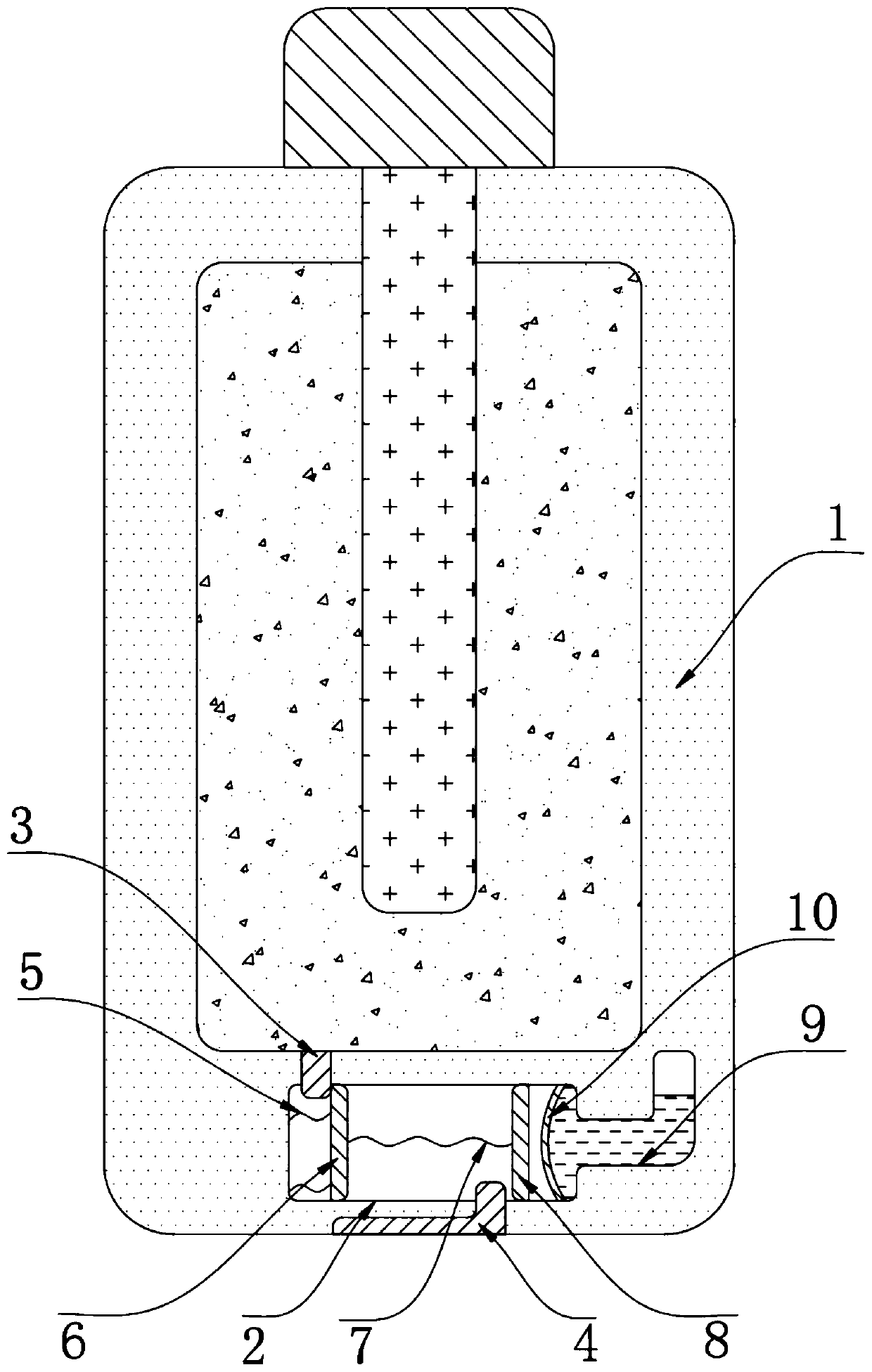
[0021] refer to figure 1 , a leak-proof battery for an air conditioner remote control, including a battery body 1 and a connecting post 3 on the battery body 1, a trigger cavity 2 is provided inside the battery body 1, and the inner wall of the trigger cavity 2 is inserted through and connected to the outer wall of the battery body 1. Fitting and "L"-shaped contact plate 4, the inner wall of the trigger chamber 2 is fixed with a connection spring 5, and the end of the connection spring 5 close to the contact plate 4 is fixed with a contact plate 6, and the end of the contact post 3 is located in the trigger chamber 2 Inside, and the electric shock plate 6 is in contact with the electric pole 3, and the end of the electric shock plate 6 away from the connection spring 5 is fixed with a contraction spring 7, and the end of the contraction spring 7 away from the electric shock plate 6 is fixed with a sliding plate 8 slidingly connected to the inner wall of the trigger chamber 2 T...

Embodiment 2

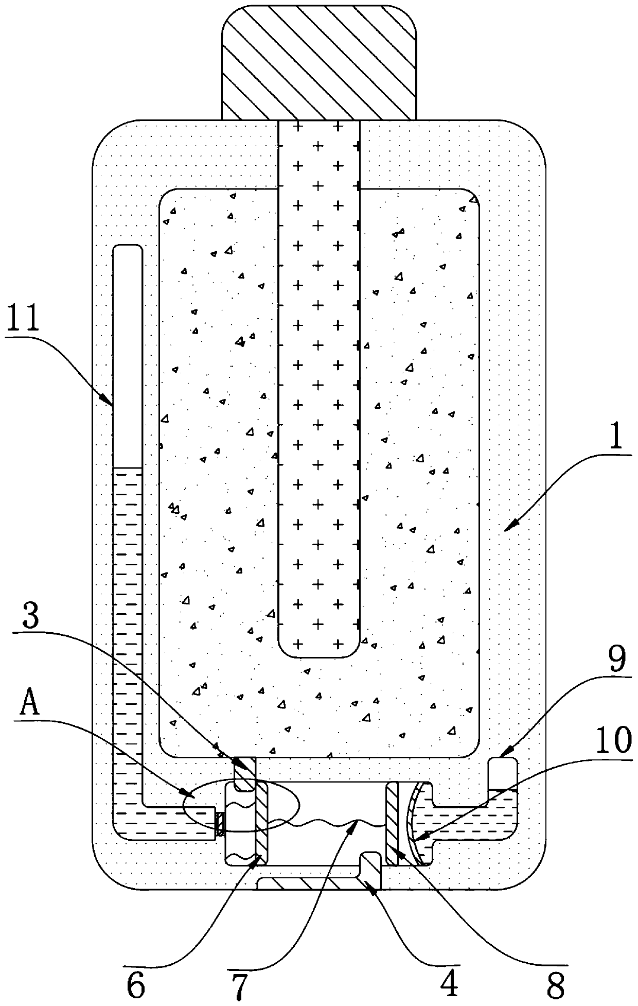
[0026] refer to Figure 2-3 , a leak-proof battery for an air conditioner remote control, including a battery body 1 and a connecting post 3 on the battery body 1, a trigger cavity 2 is provided inside the battery body 1, and the inner wall of the trigger cavity 2 is inserted through and connected to the outer wall of the battery body 1. Fitting and "L"-shaped contact plate 4, the inner wall of the trigger chamber 2 is fixed with a connection spring 5, and the end of the connection spring 5 close to the contact plate 4 is fixed with a contact plate 6, and the end of the contact plate 6 is far away from the connection spring 5 A contraction spring 7 is fixed, and the end of the contraction spring 7 away from the electric shock plate 6 is fixed with a sliding plate 8 slidingly connected to the inner wall of the trigger chamber 2 , and the side of the trigger chamber 2 away from the electric shock plate 6 is provided with a trigger device.

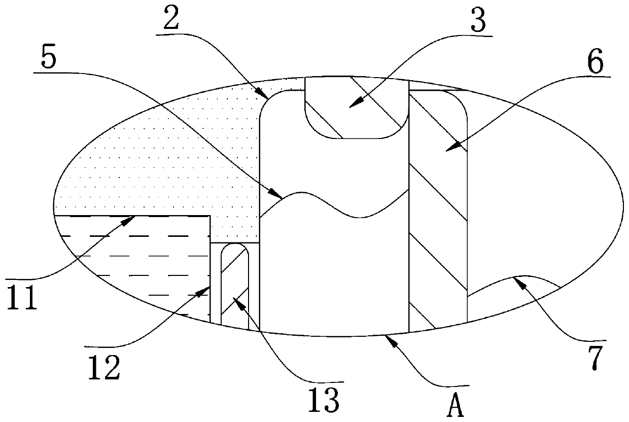
[0027] The trigger device includes a s...


PUM


Abstract

The invention discloses an anti-electric leakage battery for an air conditioner remote controller, which comprises a battery body and a power connection column on the battery body, wherein the batterybody is internally provided with a trigger cavity, an L-shaped power connection piece attached to the outer wall of the battery body is inserted into the inner wall of the trigger cavity in a penetrating manner, a connecting spring is fixed to the inner wall of the trigger cavity, an electric shock plate is fixed to the end, which is close to the power connection piece, of the connecting spring,a contraction spring is fixed to the end, which is away from the connecting spring, of the electric shock plate, and a sliding plate slidably connected with the inner wall of the trigger cavity is fixed to the end, which is away from the electric shock plate, of the contraction spring. The anti-electric leakage battery has the advantages that the power connection piece and the sliding plate are ina separated state when the battery body does not need to supply power to the outside, so that the interior of the battery body is enabled to be completely separated from the outside, micro-current caused by connection with an external circuit is avoided, electric leakage loss of the current body when the current body is not used is avoided, and the service life of the battery body is greatly prolonged.

Description

technical field [0001] The invention relates to the technical field of batteries, in particular to an anti-leakage battery for an air conditioner remote controller. Background technique [0002] Air conditioner is an air conditioner; it refers to the equipment that uses artificial means to adjust and control the temperature, humidity, flow rate and other parameters of the ambient air in a building or structure. It is an indispensable electrical appliance in people's life in modern society. [0003] The control of the air conditioner requires the use of a remote control, and the batteries used in the remote control are usually dry batteries. For electronic circuits, due to the tight coupling between components, even if there is no output at the output end, the input end will produce weak Leakage current, which will cause the dry battery to leak when the remote control is not in use, and the frequency of use of the remote control itself is not high. From a long-term perspectiv...

Claims


Application Information

Patent Timeline
IPC IPC(8): H01M2/20H01M2/34H01M50/502H01M50/584
CPCH01M2220/30H01M50/502H01M50/572Y02E60/10
Inventor 张启航
Owner 张启航
Why Eureka
Try Eureka