
Method for calculating 3dB intensity light spot radius of underwater arrival laser signal

A laser signal and spot radius technology, applied in transmission monitoring/testing/fault measurement systems, etc., can solve the problem of not fully characterizing the two-dimensional distribution characteristics of the arriving laser signal spot.

Active Publication Date: 2020-01-07
GUILIN UNIV OF ELECTRONIC TECH
View PDF4 Cites 2 Cited by
  • Summary
  • Abstract
  • Description
  • Claims
  • Application Information

AI Technical Summary

Problems solved by technology

However, in the existing research materials, there is still no related research that fully characterizes the two-dimensional distribution characteristics of the arriving laser signal spot

Method used


Image

  • Method for calculating 3dB intensity light spot radius of underwater arrival laser signal
  • Method for calculating 3dB intensity light spot radius of underwater arrival laser signal
  • Method for calculating 3dB intensity light spot radius of underwater arrival laser signal

Examples


Embodiment Construction

[0033] In order to make the object, technical solution and advantages of the present invention clearer, the present invention will be further described in detail below in combination with specific examples and with reference to the accompanying drawings.

[0034] A method for calculating the 3dB intensity spot radius of an underwater laser signal, the specific steps are as follows:

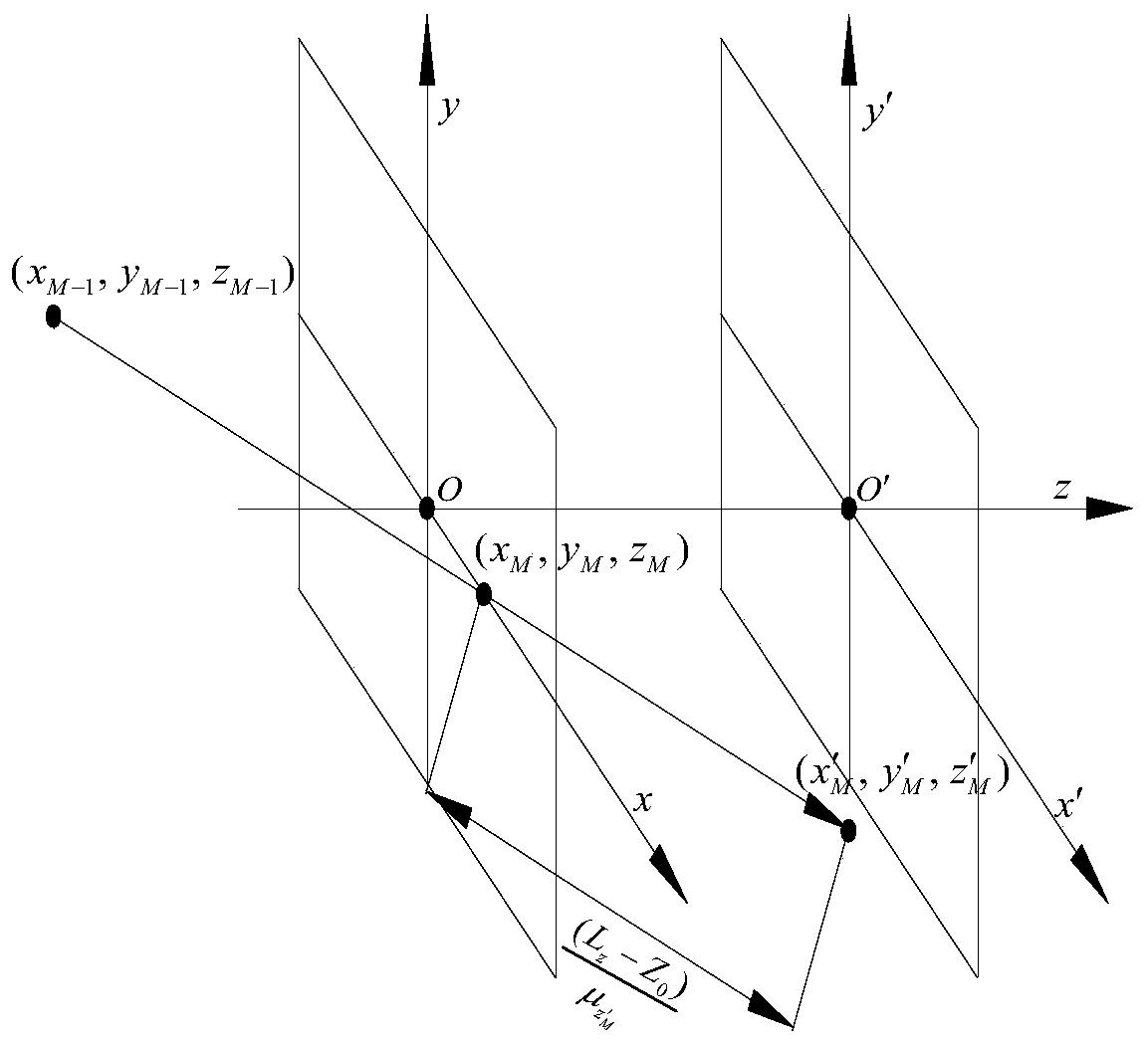
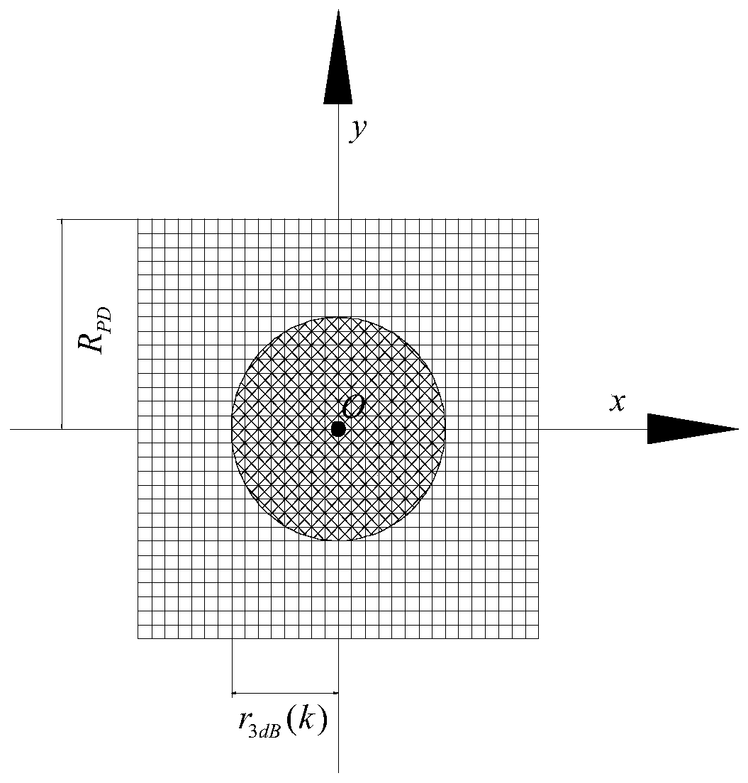
[0035] Step 1, as attached figure 1 As shown, the collimated optical axis of the transmitting and receiving antenna of the laser communication system is regarded as the z axis, and the xyz coordinate system is established based on the photon arrival plane in the actual process, that is, the receiving plane xOy, and under the given channel conditions, the seawater is simulated based on the MC simulation method The transmission process of the laser signal in MC is simulated, and the x'y'z coordinate system is established with the arrival plane of each photon in the MC simulation process, that is, th...


PUM


Abstract

The invention discloses a method for calculating a 3dB intensity light spot radius of an underwater arrival laser signal. An MC simulation platform in an underwater laser signal transmission process is established, coordinate information and power value information of photons arriving at a receiving plane are counted under a given channel condition, and photon two-dimensional distribution situation statistics is performed on the basis, so that light spots arriving at laser signals are obtained. According to the invention, data and technical references can be provided for the size design of anoptical receiving lens (including a receiving lens array) in an ocean laser communication system and an optimal position distribution strategy thereof.

Description

technical field [0001] The invention relates to the technical field of underwater laser communication, in particular to a method for calculating the 3dB intensity spot radius of an underwater arriving laser signal. Background technique [0002] The transmission process of laser light in the scattering seawater channel can be regarded as the propagation process of a large number of photons in it. In the field of underwater laser channel research, due to the complex and random space-time characteristics of seawater, the absorption effect of water molecules, phytoplankton, and colored dissolved organic matter in seawater, and the scattering effects of water molecules, phytoplankton, and suspended particles, laser signals in When propagating in seawater, it will suffer severe attenuation and deviate from the original propagation path. [0003] Due to the influence of the seawater scattering effect, the arriving laser signal will diffuse into a signal spot much larger than its n...

Claims


Application Information

Patent Timeline
IPC IPC(8): H04B10/07
CPCH04B10/07
Inventor 李晓记王伟杜卫海李燕龙符杰林仇洪冰
Owner GUILIN UNIV OF ELECTRONIC TECH
Learn More