

Landscape plant forming device
A plant and garden technology, applied in the field of garden plant shaping devices, can solve the problems of wasting manpower and time, unable to perform arc pruning, and high cost
- Summary
- Abstract
- Description
- Claims
- Application Information
AI Technical Summary
Problems solved by technology
Method used
Image

Examples
specific Embodiment approach 1
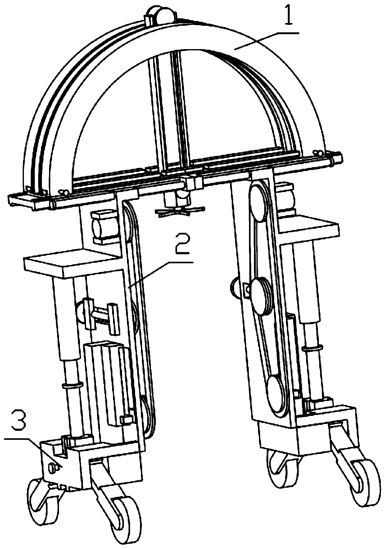
[0044] Combine below Figure 1-25 Describe this embodiment, a kind of garden plant modeling device, comprises top pruning mechanism 1, side pruning mechanism 2 and moving adjustment mechanism 3, the number of described side pruning mechanism 2 has two, is installed on top pruning mechanism 1 respectively On both sides of the side, the mobile adjustment mechanism 3 is installed on the side trimming mechanism 2.
specific Embodiment approach 2
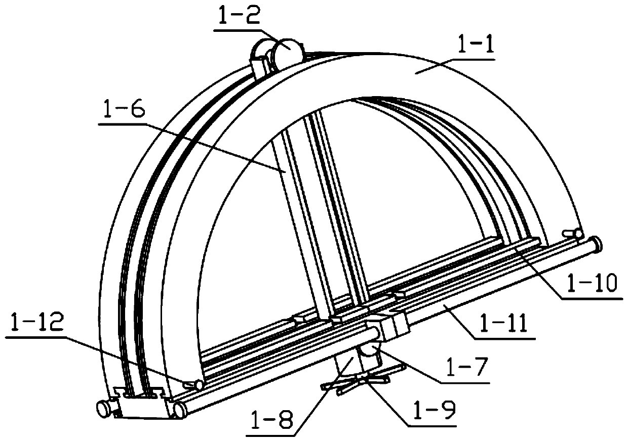
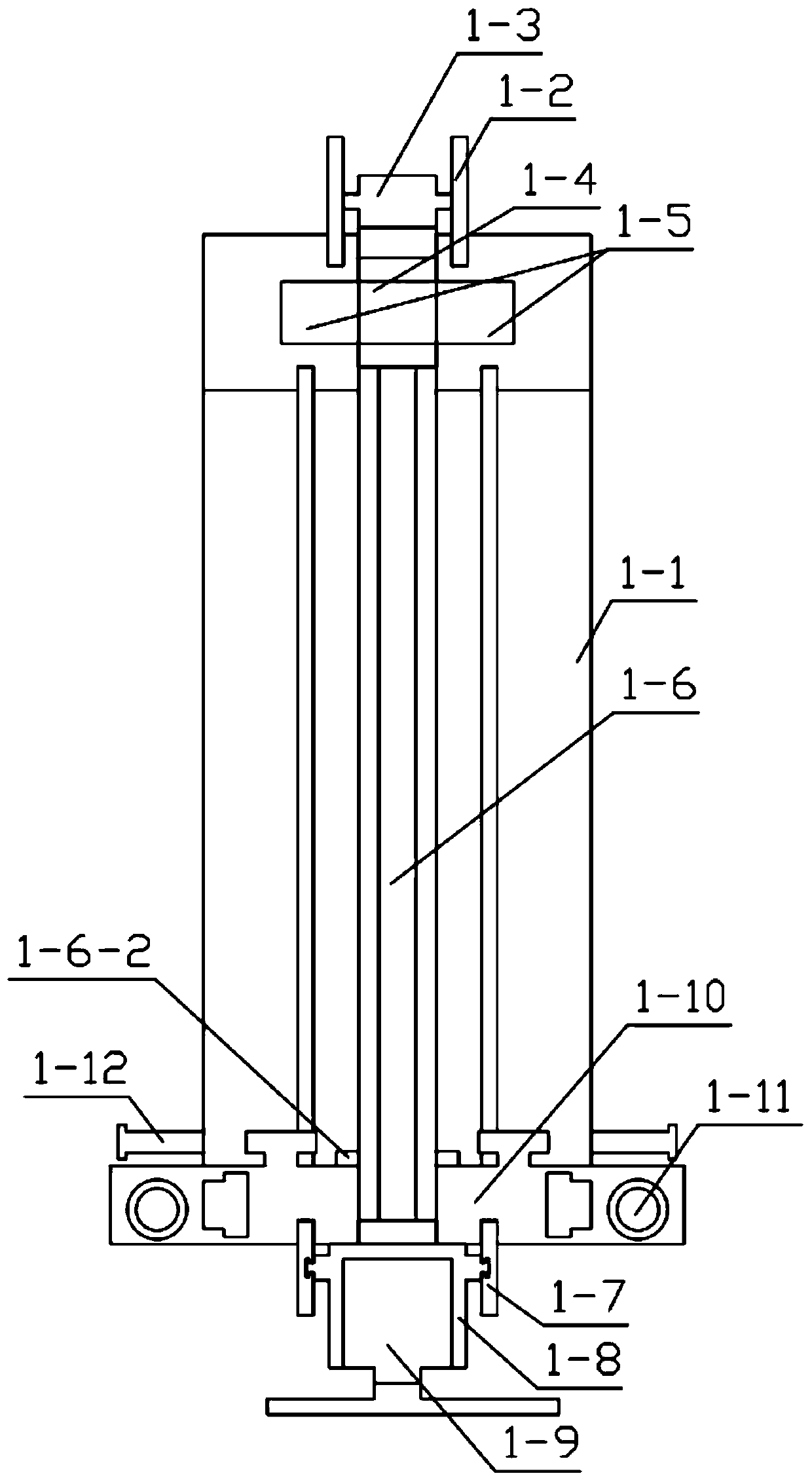
[0046] Combine below Figure 1-25 Illustrate this embodiment, and this embodiment will further illustrate Embodiment 1. The described tip trimming mechanism 1 includes an annular track plate 1-1, a moving gear 1-2, a moving motor 1-3, a swing block 1-4, and a track slide Block 1-5, U-shaped moving plate 1-6, bottom roller 1-7, motor housing 1-8, motor with fan blade 1-9, detachable beam plate 1-10, detachable two-way threaded rod 1 -11, beam limit nail 1-12, the number of moving gear 1-2 has two, respectively fixedly installed in the output end of moving motor 1-3 both sides, moving gear 1-2 and ring track plate 1-1 The grooves set on the top are meshed, the mobile motor 1-3 is fixedly installed on the swing block 1-4, the swing block 1-4 is rotatably installed on the track slider 1-5, and the track slider 1-5 is movably installed on the circular track On the groove set on the plate 1-1, the U-shaped moving plate 1-6 is movably installed on the groove set on the swing block 1...
specific Embodiment approach 3
[0048] Combine below Figure 1-25 Describe this embodiment, this embodiment will further explain the second embodiment, the side trimming mechanism 2 includes a side plate 2-1, a track slider 2-2, a limit screw 2-3, and a T-shaped slider 2 -4, trimming motor 2-5, saw chain assembly 2-6, spring movable chamber 2-7, track slider 2-2 is fixedly installed on the side plate 2-1, trimming motor 2-5 is fixedly installed on the side plate 2 On -1, the belt limit screw 2-3 is rotated and installed on the through hole provided on the side plate 2-1, the belt limit screw 2-3 is threaded with the saw chain assembly 2-6, and the spring movable chamber 2-7 is fixed Installed on the side plate 2-1, the T-shaped slider 2-4 is fixedly installed on the side plate 2-1, the saw chain assembly 2-6 is installed on the side plate 2-1, and the side plate 2-1 is detachable The two-way threaded rod 1-11 is threaded, and the track slider 2-2 is movably installed on the groove provided on the detachable...
PUM
 Abstract
Description
Claims
Application Information