Multifunctional preschool education environment-friendly equipment
A technology for preschool education and environmental protection equipment, applied in cleaning equipment, children's furniture, suction nozzles, etc., can solve problems that affect children's health, difficult to find small pieces of paper, and affect the environment
- Summary
- Abstract
- Description
- Claims
- Application Information
AI Technical Summary
Problems solved by technology
Method used
Image

Examples
Embodiment Construction
[0024] The following will clearly and completely describe the technical solutions in the embodiments of the present invention with reference to the accompanying drawings in the embodiments of the present invention. Obviously, the described embodiments are only some, not all, embodiments of the present invention. Based on the embodiments of the present invention, all other embodiments obtained by persons of ordinary skill in the art without making creative efforts belong to the protection scope of the present invention.
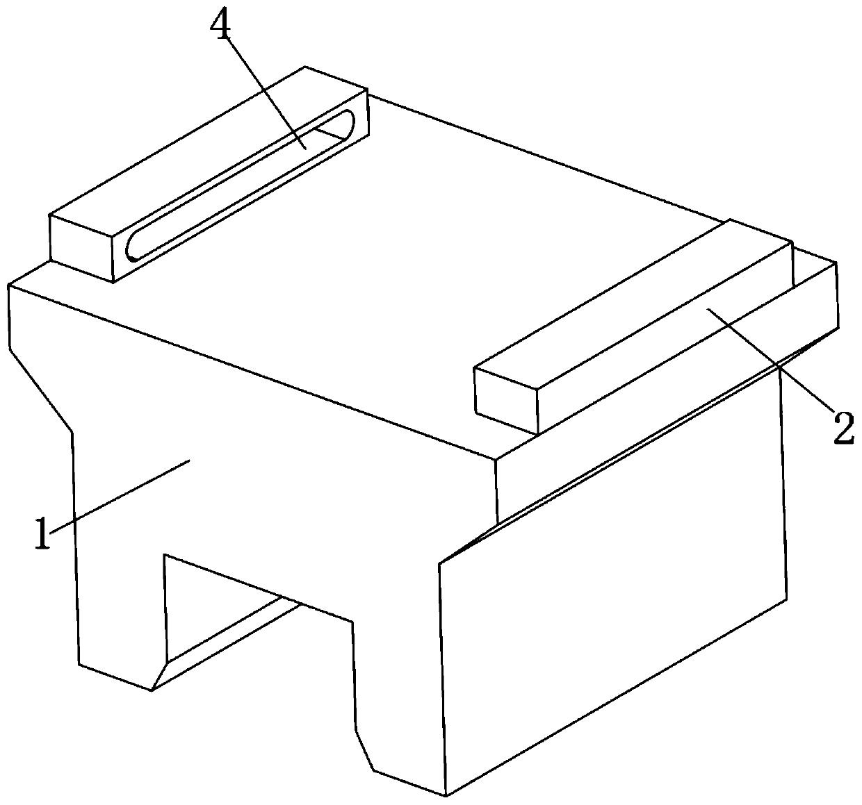
[0025] see Figure 1-7 , a multi-functional preschool education environmental protection equipment in the figure, including π-shaped block 1, which is made of ring-plate plastic, which is not easy to damage and can prevent children from accidentally touching the corners of π-shaped block 1 to cause damage;
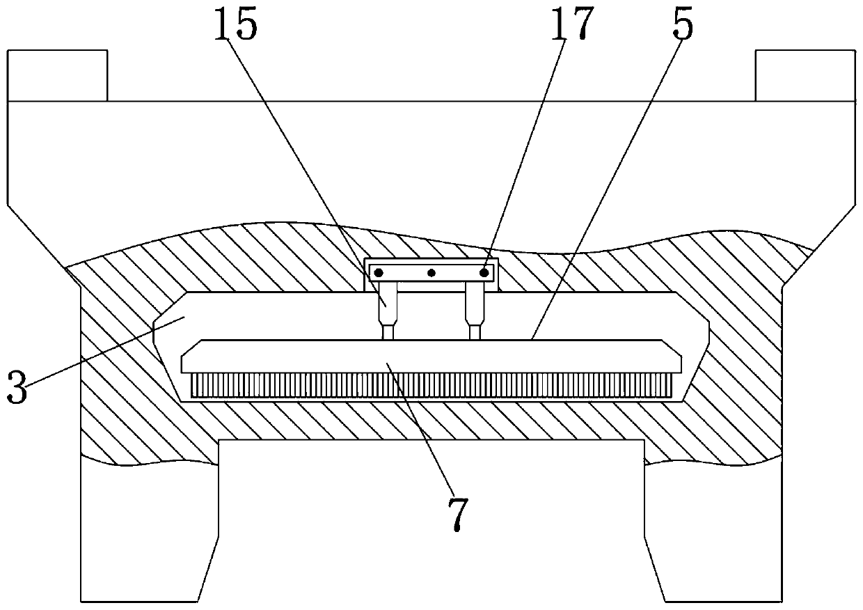
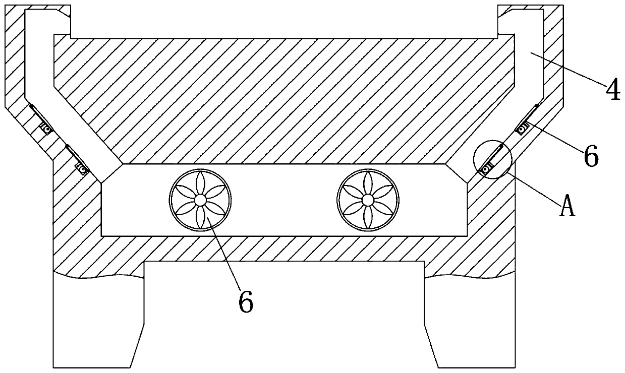
[0026] Both ends of the π-shaped block 1 are fixed with ventilation blocks 2, and the inside of the π-shaped block 1 has a collection chamber 3 and a feed...
PUM
 Abstract
Description
Claims
Application Information
PatSnap Eureka turns technology decisions into work you can execute. Powered by our Innovation Knowledge Graph, it runs expert workflows across engineering, life sciences, materials and intellectual property. Get your review-ready output in minutes.


