A mechanical keyboard cleaning device
A technology for cleaning devices and mechanical keyboards, which is applied in the directions of cleaning methods and utensils, cleaning methods using tools, chemical instruments and methods, etc., and can solve the problem that the device cannot continue to move forward for cleaning.
- Summary
- Abstract
- Description
- Claims
- Application Information
AI Technical Summary
Problems solved by technology
Method used
Image
Examples
specific Embodiment approach 1
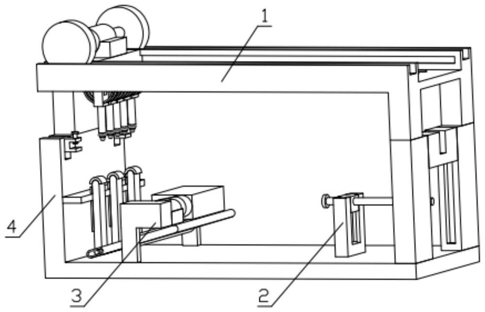
[0037] Combine below Figure 1-17 Describe this embodiment, a mechanical keyboard cleaning device, including a cleaning mechanism 1, an adjustment mechanism 2, an impact mechanism 3 and a device base 4, the impact mechanism 3 is installed on the device base 4, and the adjustment mechanism 2 is fixedly installed on the device base 4, one end of the cleaning mechanism 1 is fixedly installed on the device base 4, and the other end of the cleaning mechanism 1 is fixedly installed on the adjustment mechanism 2.
specific Embodiment approach 2
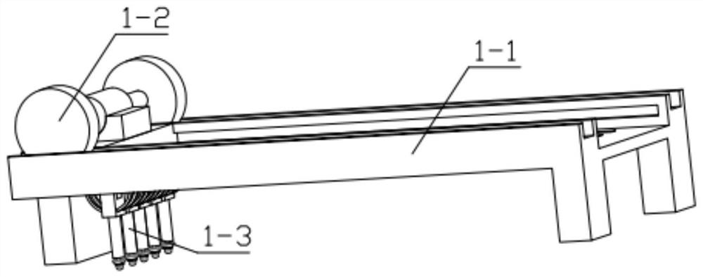
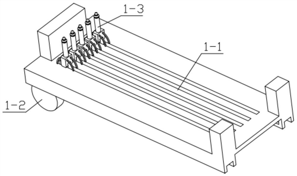
[0038] Combine below Figure 1-17Describe this embodiment, this embodiment will further explain the first embodiment, the cleaning mechanism 1 includes a track frame 1-1, a moving assembly 1-2, and a cleaning claw 1-3, and the number of cleaning claws 1-3 is five One, the cleaning claw 1-3 is hinged with the moving assembly 1-2, and the moving assembly 1-2 is movably installed on the track frame 1-1; the moving assembly 1-2 includes a sliding connector 1-2-1, a bidirectional output motor 1 -2-2, mobile gear 1-2-3, two-way output motor 1-2-2 is fixedly installed on the sliding connector 1-2-1, the number of mobile gear 1-2-3 has two, fixed respectively Installed on the output ends at both ends of the two-way output motor 1-2-2, the sliding connector 1-2-1 is movably installed on the track frame 1-1, and the moving gear 1-2-3 is meshed with the track frame 1-1; cleaning Claw 1-3 includes piece 1-3-1 with cotton ball, reverse soft brush 1-3-2, cleaning motor 1-3-3, extension col...
specific Embodiment approach 3
[0039] Combine below Figure 1-17 Describe this embodiment, this embodiment will further explain the first embodiment, the adjustment mechanism 2 includes a U-shaped carriage 2-1, a small slider 2-2, a screw 2-3, a positioning piece 2-4, a connecting Rod one 2-5, middle piece 2-6, connecting rod two 2-7, side slide plate 2-8, column 2-9, fixed clip one 2-10, small slide block 2-2 is movably installed on U-shaped slide On the frame 2-1, the screw rod 2-3 is rotatably installed on the small slider 2-2, the screw rod 2-3 is threadedly connected with the middle piece 2-6, and one end of the middle piece 2-6 is hinged with the connecting rod 2-7 , the connecting rod two 2-7 is hinged with the side slide plate 2-8, the other end of the middle piece 2-6 is hinged with the connecting rod one 2-5, and the connecting rod one 2-5 is hinged with the positioning piece one 2-4, The side slide plate 2-8 is movably installed on the groove provided on the column 2-9, and the fixed clamp part ...
PUM
 Abstract
Description
Claims
Application Information
 - R&D
- Intellectual Property
- Life Sciences
- Materials
- Tech Scout
- Unparalleled Data Quality
- Higher Quality Content
- 60% Fewer Hallucinations
Browse by: Latest US Patents, China's latest patents, Technical Efficacy Thesaurus, Application Domain, Technology Topic, Popular Technical Reports.
© 2025 PatSnap. All rights reserved.Legal|Privacy policy|Modern Slavery Act Transparency Statement|Sitemap|About US| Contact US: help@patsnap.com


