
Horse head turning and swinging mechanism for beam-pumping unit

A technology of pendulum mechanism and pumping unit, which is applied in the direction of mining fluid, wellbore/well components, earthwork drilling and production, etc. It can solve the problems of high labor intensity, high risk, and low efficiency, and achieve low labor intensity and high work efficiency Effect

Active Publication Date: 2020-01-10
CHINA UNIV OF PETROLEUM (EAST CHINA)
View PDF18 Cites 1 Cited by
  • Summary
  • Abstract
  • Description
  • Claims
  • Application Information

AI Technical Summary

Problems solved by technology

[0002] At present, the preparation work before the workover of the oil well is basically carried out by manpower. The turning of the donkey head is an important link before the workover operation. The rope device ② realizes the turning of the donkey head so that the workover rig can work at the wellhead. The donkey head is connected to the end of the beam through two pins located on both sides of the beam, and the turning of the donkey head refers to removing the pin shaft on one side , the rotation of the donkey head around the axis of the pin shaft on the other side. At present, the above two tasks are carried out manually. The inventors found that this process usually requires a lot of manpower, which is inefficient, labor-intensive, and accompanied by high risks.

Method used


Image

  • Horse head turning and swinging mechanism for beam-pumping unit
  • Horse head turning and swinging mechanism for beam-pumping unit
  • Horse head turning and swinging mechanism for beam-pumping unit

Examples


Embodiment Construction

[0026] It should be noted that the following detailed description is exemplary and intended to provide further explanation of the application. Unless otherwise defined, all technical and scientific terms used herein have the same meaning as commonly understood by one of ordinary skill in the art to which this application belongs.

[0027] It should be noted that the terminology used herein is for the purpose of describing specific embodiments only, and is not intended to limit the exemplary embodiments according to the present application. As used herein, unless the context clearly dictates otherwise, the singular is intended to include the plural as well, furthermore, it is to be understood that when the terms "comprising" and / or "including" are used in this specification, it indicates that There are features, steps, operations, devices, components and / or combinations thereof.

[0028] For the convenience of description, if the words "up", "down", "left" and "right" appear i...


PUM


Abstract

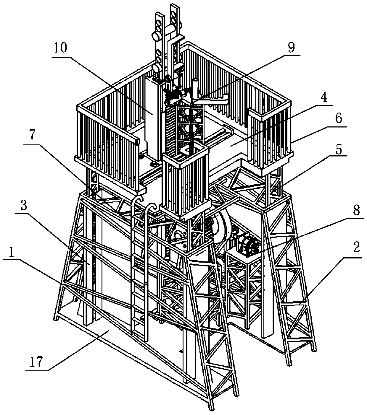
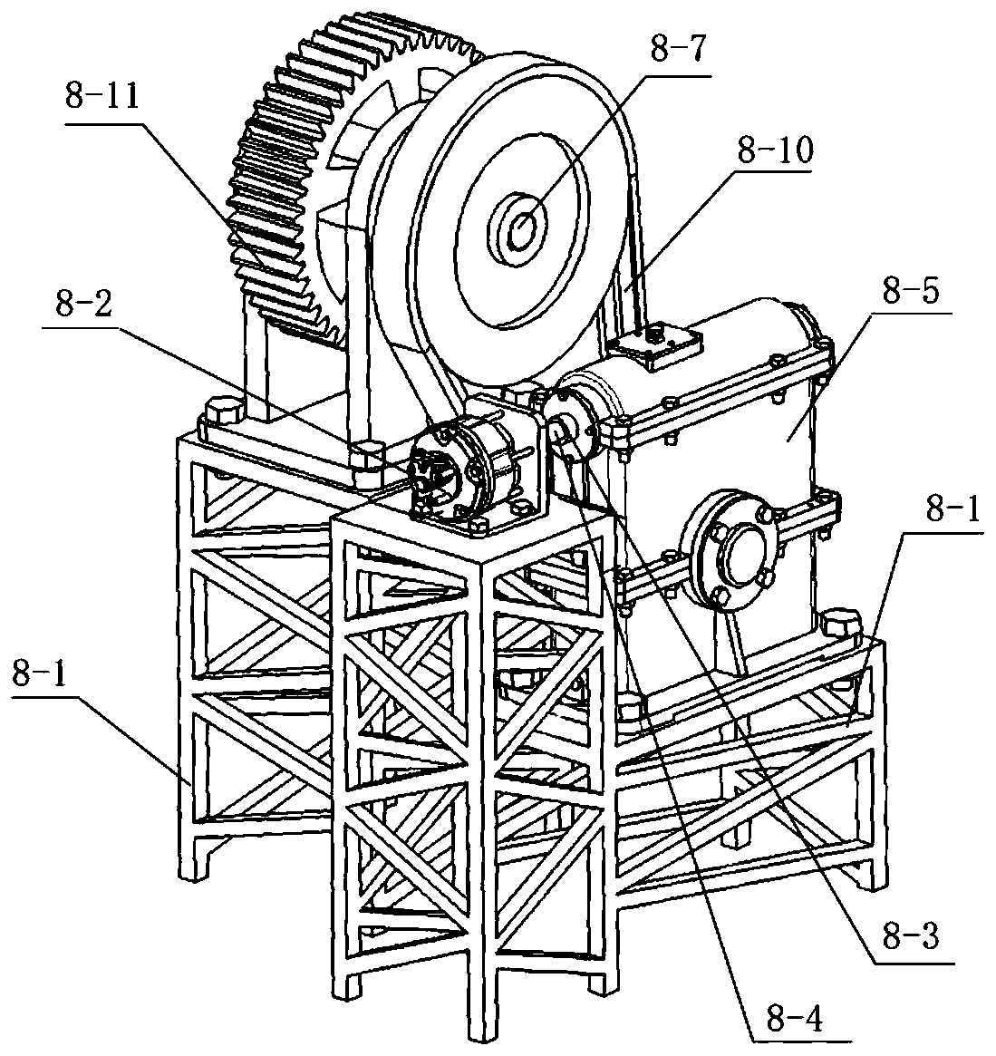
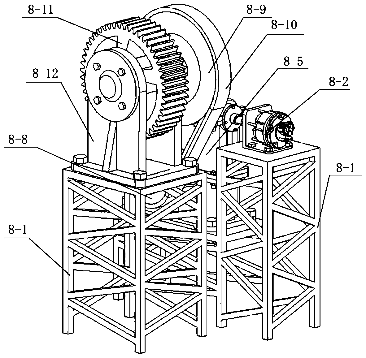
The invention relates to a horse head turning and swinging mechanism for a beam-pumping unit. The horse head turning and swinging mechanism comprises a bottom bracket, wherein the bottom bracket and alifting and lowering bracket above the bottom bracket are in sliding connection; the lifting and lowering bracket is connected with a lifting and lowering mechanism; the lifting and lowering mechanism can drive the lifting and lowering bracket to carry out lifting and lowering movement; the lifting and lowering bracket is detachably connected with a first fixing shaft and a second fixing shaft, wherein the first fixing shaft and the second fixing shaft are vertically distributed; a walking beam can pass through a space between the first fixing shaft and the second fixing shaft; the lifting and lowering bracket is connected with the turning and swinging mechanism; the turning and swinging mechanism comprises a turning and swinging bracket in sliding connection with the lifting and loweringbracket, wherein the turning and swinging bracket can move along the axial line direction of the first fixing shaft or the second fixing shaft; the turning and swinging bracket is connected with a positioning element and a turning and swinging driving mechanism; the turning and swinging driving mechanism is connected with a swinging arm; and the swinging arm is connected with a horse head. The turning and swinging mechanism is low in labor intensity and high in working efficiency.

Description

technical field [0001] The invention relates to the technical field of well workover equipment, in particular to a donkey head tilting mechanism for a beam pumping unit. Background technique [0002] At present, the preparation work before the workover of the oil well is basically carried out by manpower. The donkey head overturning is an important part before the workover operation. Generally speaking, it includes the following two parts: (1) Control the lifting and lowering of the beam to assist in the removal of the polished rod and suspension. The rope device ② realizes the swing of the donkey head to allow the workover rig to work at the wellhead. The donkey head is connected to the end of the travel beam through two pins located on both sides of the travel beam. The donkey head swing refers to removing one side pin. , the rotation of the donkey head around the axis of the pin shaft on the other side. Currently, the above two tasks are carried out manually. The inventor...

Claims


Application Information

Patent Timeline
Patent Type & Authority Applications(China)
IPC IPC(8): E21B43/00
CPCE21B43/127
Inventor 牛文杰杨梦雪宋新猛肖华芝杨珊珊英豪赵淇东
Owner CHINA UNIV OF PETROLEUM (EAST CHINA)
Learn More