
Brushless motor and unmanned aerial vehicle

A technology of brushless motors and connecting shafts, which is applied in the direction of electrical components, electromechanical devices, electric components, etc., can solve the problems of voltage deviation or skew, motor swing, propeller rotation instability, etc., to avoid scrapping, avoid motor swing, The effect of rotation stabilization

Pending Publication Date: 2020-01-10
SANGAIR TECH
View PDF0 Cites 1 Cited by
  • Summary
  • Abstract
  • Description
  • Claims
  • Application Information

AI Technical Summary

Problems solved by technology

On the UAV, the propeller is connected to the rotor of the motor; during the flight of the UAV, the high-speed rotating rotor drives the propeller to rotate. The rotor cannot continue to be used, so that the rotation of the propeller connected to the rotor is unstable. At the same time, because the rotor drives the propeller to rotate at a high speed, under the action of centrifugal force, the rotor may break away from the connecting shaft and fly out of the connecting shaft

Method used


Image

  • Brushless motor and unmanned aerial vehicle
  • Brushless motor and unmanned aerial vehicle
  • Brushless motor and unmanned aerial vehicle

Examples


Embodiment Construction

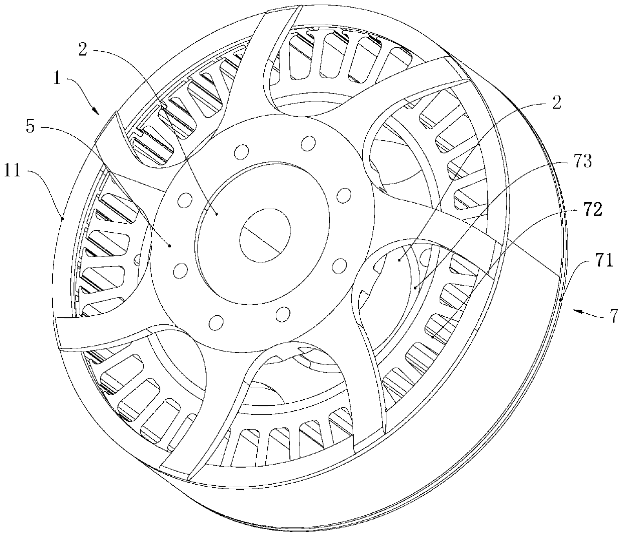
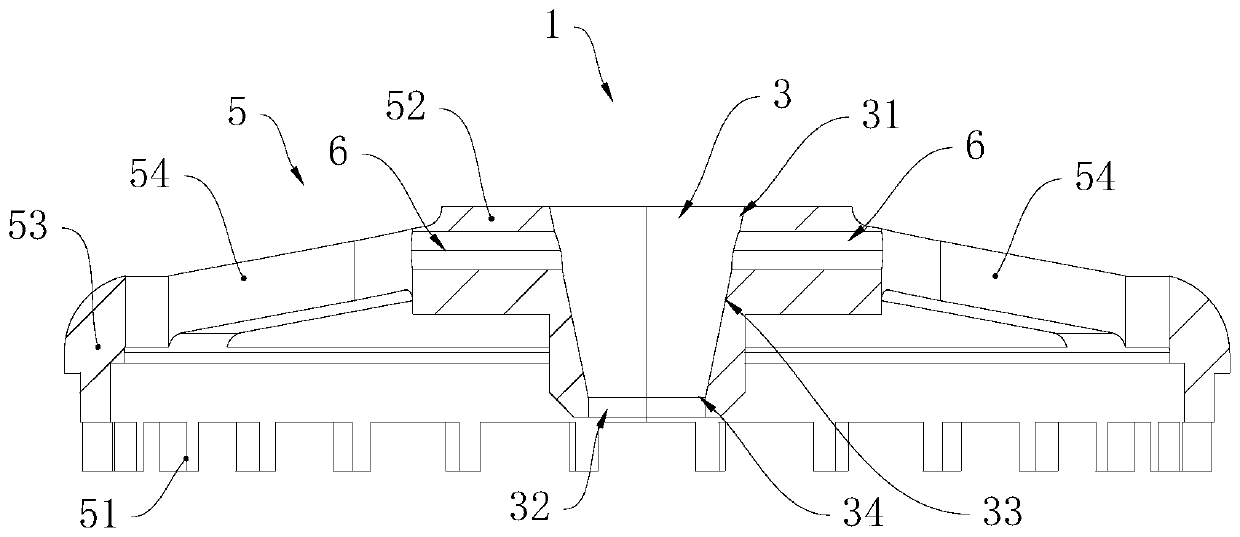
[0030] see figure 1 , The brushless motor includes a stator 7, a rotor 1 and a connecting shaft 2, and the rotor 1 rotates relative to the stator 7. The stator 7 includes a bearing seat 71, a silicon steel sheet 72 and a bearing 73. The bearing seat 71 supports a silicon steel sheet 72, and the bearing seat 71 supports a bearing 73. The silicon steel sheet 72 is provided with a coil; the connecting shaft 2 is arranged in the bearing 73. The rotor 1 includes a back cover 5, a casing 11 and a magnetic sheet. The magnetic sheet is evenly arranged on the inner peripheral wall of the casing 11. The casing 11 is arranged along the edge of the bearing seat 71. The magnetic sheet is arranged on the periphery of the silicon steel sheet 72. The back cover 5 is provided with a plurality of raised strips, and one raised strip is arranged between two adjacent magnetic pieces. In this embodiment, the raised strip is arranged on the side of the back cover 5 facing the stator 7 .

[0031] se...


PUM


Abstract

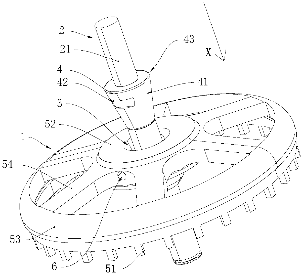
The invention provides a brushless motor and an unmanned aerial vehicle. The unmanned aerial vehicle comprises the brushless motor; the brushless motor comprises a stator, a rotor and a connecting shaft; the rotor rotates relative to the stator; the connecting shaft is connected with the stator; a mounting through groove is formed in the rotor; the mounting through groove comprises a guide section; the cross section of the guide section is trapezoidal; the connecting shaft comprises a connecting shaft body and a guide block; the guide block is arranged on the periphery of the connecting shaftbody; the connecting shaft body is cylindrical; a conical surface is arranged at the outer side wall of the guide block; the guide block is arranged in the guide section in an interference manner; andthe radial width of the outer end part of the guide block is greater than that of the inner end part of the guide section. With the above structure adopted, by the adoption of the structure, under the guiding effect of the guiding section, the situation that the connecting shaft is pressed to deviate or incline is avoided, so that the scrapping of the rotor and the swing of the motor are avoided;and therefore, a propeller connected with the rotor rotates more stably, the rotor cannot be disengaged from the connecting shaft in the high-speed rotating process of the rotor, and the situation that the rotor flies out is avoided.

Description

technical field [0001] The invention relates to the field of power generation devices, in particular to a brushless motor and an unmanned aerial vehicle. Background technique [0002] At present, the motor shafts of brushless motors on the market are polished straight shafts. During the motor production process, since most of the motor rotors and motor shafts are interference fit, the motor shaft needs to be installed on the on the rotor. On the UAV, the propeller is connected to the rotor of the motor; during the flight of the UAV, the high-speed rotating rotor drives the propeller to rotate. This rotor cannot continue to be used, thereby makes the rotation of the propeller connected to the rotor unstable. At the same time, because the rotor drives the propeller to rotate at a high speed, under the action of centrifugal force, the rotor may break away from the connecting shaft and fly out from the connecting shaft. Contents of the invention [0003] The first object of ...

Claims


Application Information

Patent Timeline
Patent Type & Authority Applications(China)
IPC IPC(8): H02K7/00H02K1/22H02K7/14H02K7/08H02K1/30H02K5/16H02K29/00B64D27/24
CPCB64D27/24H02K1/22H02K1/30H02K5/16H02K7/003H02K7/08H02K7/14H02K29/00
Inventor 欧阳兆昌
Owner SANGAIR TECH
Learn More