Feeding device of aluminum foil slitting machine

A technology of slitting machine and aluminum foil, which is applied in the direction of winding strips, thin material handling, transportation and packaging, etc., can solve the problems of affecting the slitting process, inconvenient shaft rotation, larger outer diameter, etc., to achieve operation and control. Convenience, stable fixation of raw materials, and uniform tightening force

Pending Publication Date: 2020-01-14
山东富格琳遮阳科技有限公司
View PDF0 Cites 2 Cited by
  • Summary
  • Abstract
  • Description
  • Claims
  • Application Information

AI Technical Summary

Problems solved by technology

[0002] When the aluminum foil cutting machine is feeding, a shaft passes through the center hole of the raw material, and the raw material is transported to the feeding machine. The feeding and transportation of the raw material are all manually operated, which is time-consuming and laborious. Inconvenient to rotate
[0003] The existing aluminum foil feeding machine fixes the raw material by setting a cone head or a cone shaft at both ends of the center hole of the material. The two ends of the center hole realize the fixing of the raw material, but in the process of cutting the aluminum foil, as the raw material gradually decreases, the cylindrical raw material formed by the aluminum foil becomes thinner and thinner, while the pressure of the cone shaft remains constant, the cylindrical The raw material cannot withstand the pressure of the cone shaft, and the outer diameter of the cylindrical raw material gradually increases at the part in contact with the cone shaft. Because the cylindrical raw material is rotating during the cutting process, the outer diameter of the cylindrical raw material becomes larger, so that the cone shaft and The force between the raw materials causes the raw materials to be unable to be fixed and stable, which affects the normal operation of the cutting process

Method used


Image

  • Feeding device of aluminum foil slitting machine
  • Feeding device of aluminum foil slitting machine
  • Feeding device of aluminum foil slitting machine

Examples


Embodiment Construction

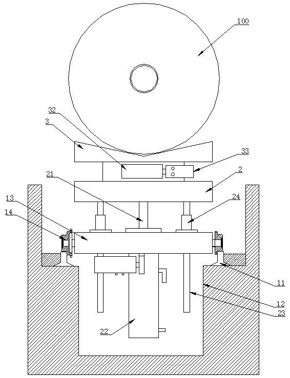
[0042] like Figure 1 to Figure 5 Shown, a kind of aluminum foil slitting machine feeding device comprises:

[0043] The rotary trolley and its walking guide rail 11 used for transporting raw materials, the walking guide rail 11 is installed in the traveling groove 12, the traveling groove 12 is a groove opened on the ground, and the traveling groove is formed by masonry building or concrete pouring in the groove. Groove 12, the top surface of travel groove 12 is flush with ground.

[0044] For the feeding machine for loading raw materials 100, the end point of the walking guide rail 11 extends to one side of the feeding machine.

[0045] Rotary trolley includes:

[0046] The traveling mechanism includes a traveling base 13 and traveling wheels 14, and the traveling wheels 14 are driven by a power mechanism to move along the traveling guide rail 11.

[0047] The lifting platform 2 and the lifting mechanism driving the lifting platform 2 to lift, the lifting platform 2 is lo...


PUM


Abstract

The invention relates to a feeding device of an aluminum foil slitting machine. The feeding device comprises a rotary trolley used for transporting raw materials, walking guide rails of the rotary trolley and a feeding machine used for loading the raw materials. The rotary trolley comprises a walking mechanism moving along the walking guide rails, a lifting platform, a hoisting mechanism used fordriving the lifting platform to ascend and descend, a rotary platform used for containing the materials and a rotary mechanism used for driving the rotary platform to rotate. The feeding machine comprises a machine seat and a tension mechanism. The tension mechanism comprises multiple arc plates, an expansion-shrinkage pull rod shaft, a core shaft and a first power device. The first power device drives the expansion-shrinkage pull rod shaft to stretch and shrink, so that the multiple arc plates are expanded outwards or loosened inwards. According to the feeding device, feeding is convenient, the raw materials are fixed stably, operation is coordinated with the aluminum foil slitting procedure in order, and it is guaranteed that the aluminum foil slitting procedure is carried out fast in order; the rotary trolley is arranged, time and labor are saved during feeding, and operation is not limited by sites; and the feeding machine is provided with the tension mechanism, the raw materials are fixed, operation and control are more convenient, and tension force is constant.

Description

technical field [0001] The invention relates to the technical field of mechanical equipment, in particular to a feeding device for an aluminum foil slitting machine. Background technique [0002] When the aluminum foil cutting machine is feeding, a shaft passes through the center hole of the raw material, and the raw material is transported to the feeding machine. The feeding and transportation of the raw material are all manually operated, which is time-consuming and laborious. Rotation is inconvenient. [0003] The existing aluminum foil feeding machine fixes the raw material by setting a cone head or a cone shaft at both ends of the center hole of the material. The two ends of the center hole realize the fixing of the raw material, but in the process of cutting the aluminum foil, as the raw material gradually decreases, the cylindrical raw material formed by the aluminum foil becomes thinner and thinner, while the pressure of the cone shaft remains constant, the cylindri...

Claims


Application Information

Patent Timeline
Patent Type & Authority Applications(China)
IPC IPC(8): B65H19/12B65H35/02
CPCB65H19/12B65H35/02B65H2701/1133B65H2701/1732
Inventor 邱冠华邱法金张明吉
Owner 山东富格琳遮阳科技有限公司
Why Eureka
Try Eureka