
Full-dynamic seat back synchronous linkage device

A synchronous linkage, full dynamic technology, applied to other seating furniture, chairs with vertically adjustable seats, stools, etc., can solve the problems of complex installation, insufficient versatility, and difficulty in mass production, and achieve convenient assembly, Overall strong effect

Inactive Publication Date: 2020-01-17
UE FURNITURE CO LTD
View PDF2 Cites 0 Cited by
  • Summary
  • Abstract
  • Description
  • Claims
  • Application Information

AI Technical Summary

Problems solved by technology

[0010] Although the above-mentioned seats can swing from side to side, they are equipped with a large number of rubber parts and a relatively complicated linkage mechanism, and the installation is also relatively complicated. The versatility is not enough, and it is difficult to achieve mass production

Method used


Image

  • Full-dynamic seat back synchronous linkage device
  • Full-dynamic seat back synchronous linkage device
  • Full-dynamic seat back synchronous linkage device

Examples


Embodiment 1

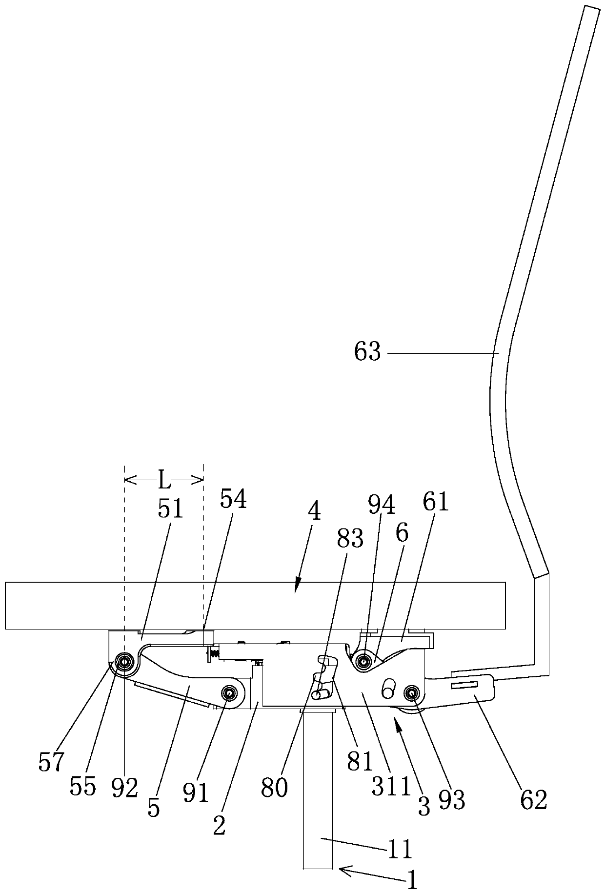
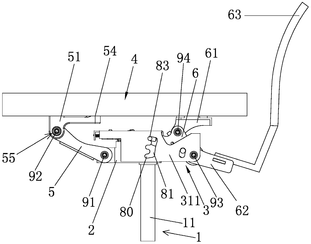
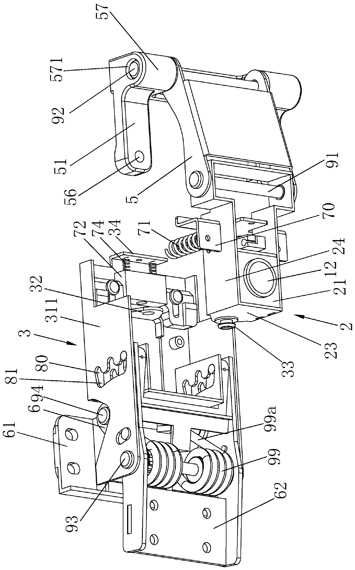
[0064] Embodiment 1: The full dynamic seat back synchronous linkage device of the present invention is an integral part of the seat, and the whole seat is described in detail next, so that the present invention and its application can be understood more clearly and appropriately; as Figure 1-18 As shown, the seat includes:

[0065] The first base 2 configured to connect the seat support assembly 1, the first base 2 includes a bottom plate 21 and a front plate 22 and a rear plate 23 extending upward from the front and rear ends of the bottom plate 21, the front plate 22 , The rear plate 23 plays a supporting role; the seat support assembly 1 includes a support rod 11 and a support foot (not shown), and a socket 12 is correspondingly provided on the bottom plate 21, and the support rod 11 is arranged in the socket 12 , the support rod 11 and the support feet are standing on the ground, so the first base 2 is kept horizontal and fixed relative to the ground except that it rotate...

Embodiment 2

[0087] Embodiment 2: The difference with Embodiment 1 is that, as Figure 19 As shown, the two elastic connectors 51 in this embodiment are independent components, which is designed to facilitate layout, and on the basis of meeting the requirements, it saves materials and reduces costs.

Embodiment 3

[0088] Embodiment 3: The difference from Embodiment 1 is that the second base 3 rotates around the first base 2 through the rotating shaft 33, the rotating shaft 33 is a whole long axis, and the swing reset mechanism in this embodiment is sleeved The torsion spring (not shown) on the above-mentioned rotating shaft 33 has two torsion springs, one torsion arm of the torsion spring is connected to the base, and the other torsion arm of the torsion spring is connected to the left or right side of the top plate 31; it is realized by the torsion spring The rotation of the second base 3 resets.


PUM


Abstract

The invention relates to a full-dynamic seat back synchronous linkage device which comprises: a first base configured to connect with a seat supporting assembly; a second base that is connected with the first base in a left-right rotating mode; a bracket that is used for being connected with a seat supporting piece, is arranged above the first base and the second base, and is divided into a rigidpart and a flexible part, and wherein the rigid part and the flexible part are connected together; a first crank, wherein one end of the first crank is hinged to the first base, and the other end of the first crank is hinged with the flexible part; a second crank, wherein one end of the second crank is hinged to the second base, and the other end of the second crank is hinged to the rigid part; awarped plate that is configured to be connected with a chair back assembly, and the warped plate and the second crank are connected into a whole. The bracket is divided into the rigid part and the flexible part, the flexible part can be twisted and deformed, and the rigid part and the flexible part are connected together, so that the bracket is stronger in integrity and convenient to assemble withthe seat supporting piece, and parts are not scattered.

Description

technical field [0001] The invention relates to the field of seats, in particular to a full dynamic seat-back synchronous linkage device. Background technique [0002] The seat chassis, also known as the seat tray, is an important part installed under the seat cushion. The lifting of the seat cushion and the adjustment of the tilt angle of the backrest are all done by the chassis. [0003] Since the human body will change various postures when sitting, it is necessary for the back of the chair to move back and forth following the back of the human body to make the back of the human body feel more comfortable; Adaptive seat. [0004] For example: Patent No. CN201320715928.9 discloses "a novel self-adaptive elastic seat", comprising a chair back frame, a headrest mounted on the top of the chair back frame, mounted on the chair back frame and positioned on the headrest As for the chair back below, the chair back includes a plurality of chair back strips, the chair back strips...

Claims


Application Information

Patent Timeline
Patent Type & Authority Applications(China)
IPC IPC(8): A47C7/02A47C7/44A47C3/24A47C3/18A47C3/025
CPCA47C3/025A47C3/18A47C3/24A47C7/02A47C7/443
Inventor 叶金金明华阮正富
Owner UE FURNITURE CO LTD
Learn More