
Grinding mechanism, grinding machine and grinding method

A grinding mechanism and grinding machine technology, applied in the grinding field, can solve the problems of reducing manufacturing costs, assembly errors affecting the size of the thickness, disadvantages, etc., and achieve the effects of reducing manufacturing costs, all-round cleaning, and simple structure

Pending Publication Date: 2020-01-17
金文 +1
View PDF0 Cites 5 Cited by
  • Summary
  • Abstract
  • Description
  • Claims
  • Application Information

AI Technical Summary

Problems solved by technology

[0003] (1) For the traditional grinding machine, because the dynamically rotating lower grinding disc assembly is fixedly connected to the motor, it is in a completely fixed state and cannot be disassembled, that is, the user can only remove the static upper grinding disc assembly located on the upper part. Therefore, the traditional The cleaning work of the grinder is quite troublesome, and it is even impossible to clean it thoroughly. If things go on like this, it will not only affect the taste of the coffee liquid, but also bring greater health risks
[0004] (2) The traditional grinder usually can only grind coffee powder of one thickness specification, which cannot meet the needs of users with different tastes for different thicknesses. Moreover, because there are many assembly parts in the grinding mechanism, the assembly error It will also affect the thickness, which is not conducive to ensuring product quality
[0005] (3) The structure of the traditional grinding machine is relatively complicated, and the manufacturing process is cumbersome, which is not conducive to reducing the manufacturing cost

Method used


Image

  • Grinding mechanism, grinding machine and grinding method
  • Grinding mechanism, grinding machine and grinding method
  • Grinding mechanism, grinding machine and grinding method

Examples


Embodiment 1

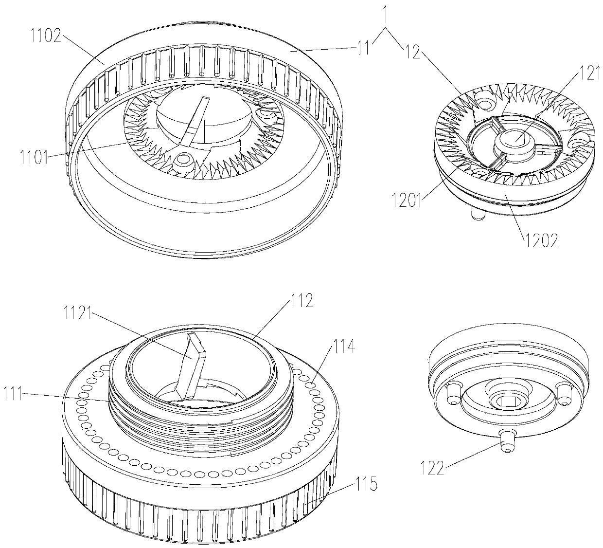
[0107] A grinding mechanism 1, such as figure 1 As shown, an upper grinding disc assembly 11 and a lower grinding disc assembly 12 are included, which are arranged independently.

[0108] Wherein, the upper grinding disc assembly 11 is provided with a connecting part that can be detachably connected to the outside, and the exterior may be a specific bracket 28 or a shell, and also other parts that can fix the upper grinding disc assembly 11.

[0109] The lower grinding disc assembly 12 receives an external drive to rotate and can be independently detached. The external drive can be manual drive or electric drive, for example, it can be rotated by hand, or it can be driven by a motor connection.

[0110] It can be seen from the above structure that both the upper grinding disc assembly 11 and the lower grinding disc assembly 12 can be disassembled separately for thorough cleaning, which can prevent the coffee powder from accumulating on the upper grinding disc assembly 11 and / or the lo...

Embodiment 2

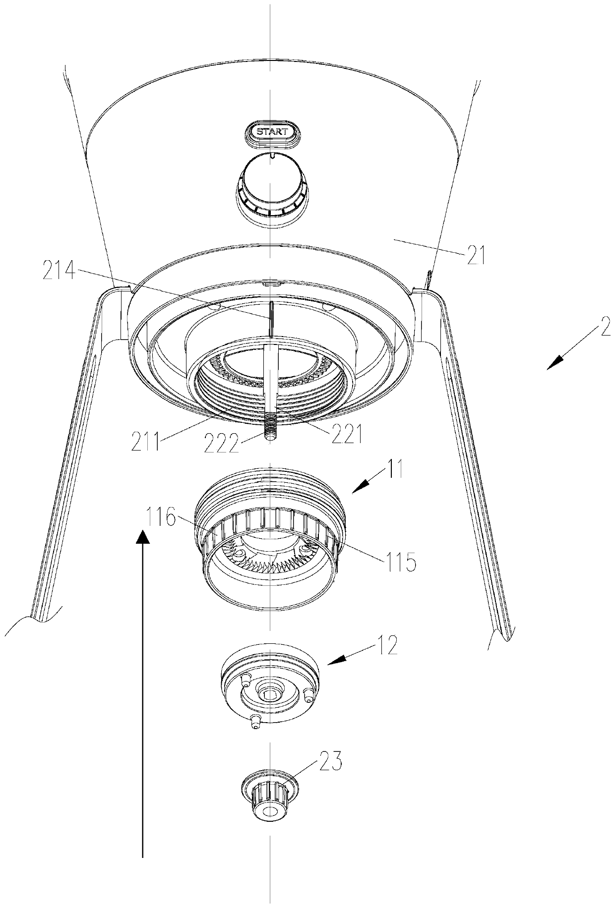
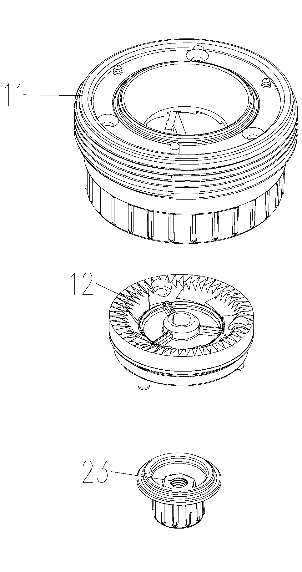
[0118] This embodiment discloses a grinder 2, which has the advantages of stably adjusting the thickness of coffee powder, being able to clean thoroughly, and having a simple structure, such as Figure 1 to 12 As shown, it includes a host 21, a driving mechanism 22, and the grinding mechanism 1 of the first embodiment.

[0119] Such as figure 2 , The upper grinding disc assembly 11 is detachably connected to the host 21 through the connecting portion, and the upper grinding disc assembly 11 can move upward along its axial direction to a state of extreme tight fit with the host 21. The lower grinding disc assembly 12 can be detachably connected with the driving mechanism 22 and rotates with the driving mechanism 22. When the lower grinding disc assembly 12 is connected in place and the upper grinding disc assembly 11 and the host 21 are in a tightly matched state, the grinding gap is the maximum.

[0120] To make the ground coffee powder finer, you only need to adjust the upper gri...

Embodiment 3

[0171] This embodiment discloses another grinding machine 2, which is different from the grinding machine 2 of embodiment 2 in:

[0172] In this embodiment, the upper grinding disc assembly 11 is provided with a plurality of retractable first mandrels 113, and the main body 21 is provided with a plurality of first recesses 212; the upper grinding disc assembly 11 is connected with the main body 21 to enable the grinding When the gap reaches the set requirement, each first mandrel 113 and each first recessed portion 212 respectively cooperate to limit and fix the upper grinding disc assembly 11 and prevent the upper grinding disc assembly 11 from rotating. Such as Figure 13 with Figure 14 As shown, the upper grinding disc assembly 11 is provided with a blind hole for the first mandrel 113 to be installed and extended. After adjusting the position of the upper grinding disc assembly 11, the first top rod 113 extends into the first recess 212, so that the upper grinding disc assem...


PUM


Abstract

The invention discloses a grinding mechanism which can be used for grinding coffee beans and the like and comprises an upper grinding disc assembly and a lower grinding disc assembly which are independently arranged. The upper grinding disc assembly is provided with a connecting part which can be detachably connected with the outside, and the lower millstone assembly is driven by the outside to rotate and can be independently detached; the upper millstone assembly and the lower millstone assembly are matched with each other to form a grinding gap; the upper millstone assembly can move in the axial direction of the upper millstone assembly to adjust the size of a grinding gap; when the lower grinding disc assembly is installed in place and the upper grinding disc assembly moves upwards in the axial direction of the upper grinding disc assembly to be in a limit close fit state with the outside, the grinding gap is the maximum value. Correspondingly, the invention further discloses a grinding machine applying the grinding mechanism and a grinding method applying the grinding machine. According to the invention, the fineness of coffee powder can be stably adjusted, thorough and all-around cleaning can be achieved, and the structure is simple. In addition, the corresponding grinding method is convenient and simple to operate and good in user experience.

Description

Technical field [0001] The invention belongs to the technical field of grinding, and specifically relates to a grinding mechanism, a grinding machine and a grinding method. Background technique [0002] With the gradual development of the national economy, people have higher and higher requirements for the quality of life, and coffee as a daily drink has entered many ordinary families. The key to the quality of coffee lies in the quality of the coffee beans, but the taste of coffee still depends on the freshness of the coffee powder. Because even high-quality coffee beans, if they are ground into coffee powder and left for a certain period of time, their quality will decrease. Based on this, more and more loyal coffee enthusiasts are more willing to bring their own coffee bean grinders to obtain fresher coffee powder by grinding coffee beans by themselves. However, the traditional grinder has the following problems: [0003] (1) For traditional grinders, since the lower grinding...

Claims


Application Information

Patent Timeline
IPC IPC(8): A47J42/16A47J42/20A47J42/46A47J42/56A47J42/38
CPCA47J42/16A47J42/20A47J42/38A47J42/46A47J42/56
Inventor 金文胡伟
Owner 金文
Learn More