A stamping equipment for mechanical stamping parts

A technology for mechanical stamping and stamping equipment, applied in the field of stamping equipment, can solve the problems of high cost, difficult to popularize, complicated device structure, etc., and achieve the effects of low cost, simple structure and convenient use.

Active Publication Date: 2020-11-03
RUIAN VEHICLE FITTING FACTORY
View PDF10 Cites 0 Cited by
  • Summary
  • Abstract
  • Description
  • Claims
  • Application Information

AI Technical Summary

Problems solved by technology

However, the structure of the device is relatively complicated, and the discharge structure needs to be set and driven separately, and the cost is relatively high, so it is difficult to popularize

Method used


Image

  • A stamping equipment for mechanical stamping parts
  • A stamping equipment for mechanical stamping parts
  • A stamping equipment for mechanical stamping parts

Examples


Embodiment 1

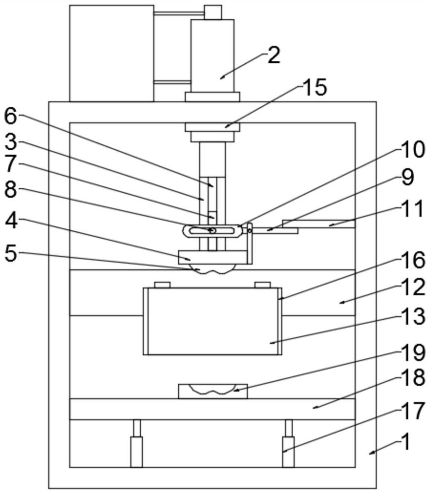
[0020] Example 1: Please refer to Figure 1-3 , a stamping equipment for mechanical stamping parts, including a frame 1, a hydraulic cylinder 2 is fixedly connected to the top of the frame 1, a connecting rod 3 is fixedly connected to the output end of the hydraulic cylinder 2, and the bottom of the connecting rod 3 is fixedly connected through a horizontal seat 4 There is stamping upper die 5;

[0021] When in use, the hydraulic cylinder 2 is turned on, and the plunger rod at the output end of the hydraulic cylinder 2 moves up and down to drive the connecting rod 3 to move up and down, thereby stamping the iron plate to be processed into the required shape, and automatically goes up after the stamping is completed;

[0022] The connecting rod 3 is made of non-ferromagnetic material, the middle part of the connecting rod 3 is provided with a chute 6, the inside of the chute 6 is slidably connected with a magnet 7, and the middle part of the front side of the magnet 7 is fixedl...

Embodiment 2

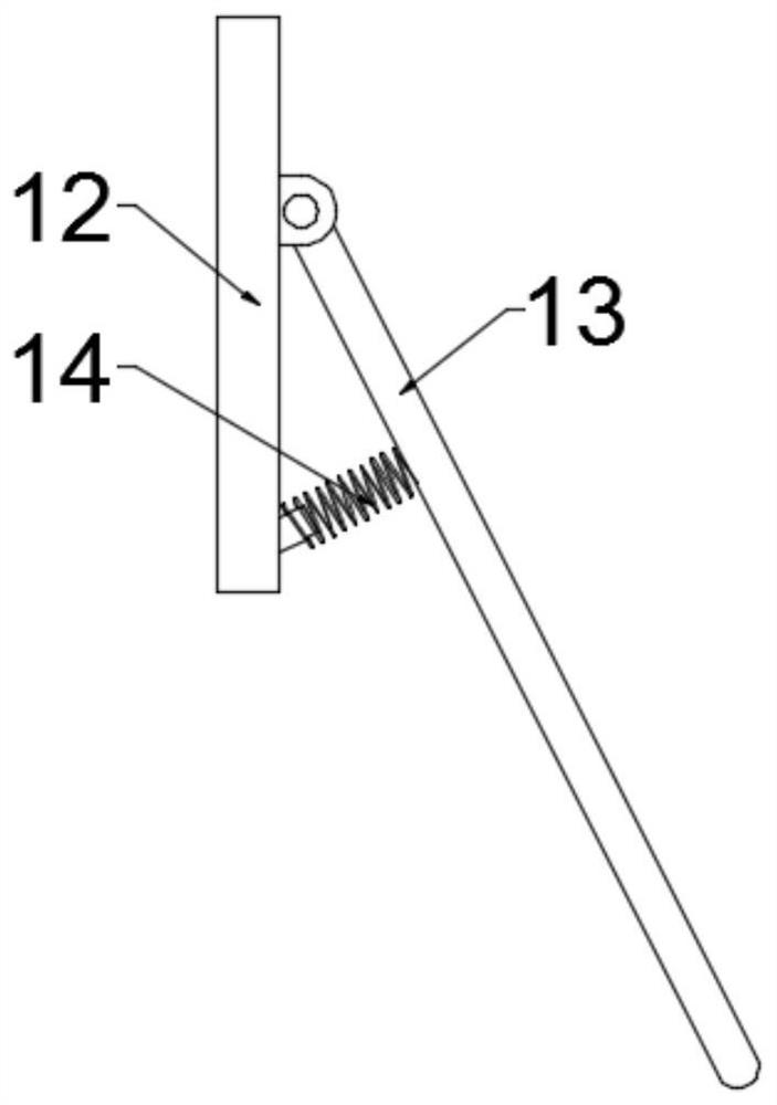
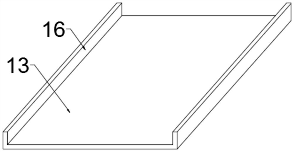
[0032] Embodiment 2: This embodiment is a further improvement of the previous embodiment: both sides of the material guide plate 13 are fixedly connected with material guide ribs 16 . The setting of the material guide rib 16 can prevent the stamping parts from falling sideways, and facilitate the collection of stamping parts.

[0033] The working principle of the present invention is: when in use, the hydraulic cylinder 2 is opened, and the plunger rod at the output end of the hydraulic cylinder 2 moves up and down to drive the connecting rod 3 to move up and down, thereby punching the iron plate to be processed into a required shape, and automatically after the stamping is completed. Up, when going up, the magnet 7 will absorb the stamping parts and drive up synchronously, when the swing rod 9 intersects with the limit stop rod 11 when it goes up, the swing rod 9 will be in the position of the limit stop rod 11 when it continues to go up Rotating downward, the magnet 7 will g...


PUM


Abstract

The invention discloses stamping equipment used for mechanical stamped parts, and relates to stamping equipment. The stamping equipment comprises a frame, a hydraulic oil cylinder is fixedly connectedto the top of the frame, a connecting rod is fixedly connected to the output end of the hydraulic oil cylinder, a stamping upper die is fixedly connected to the bottom of the connecting rod through ahorizontal seat, the connecting rod is made of a nonferromagnetic material, a sliding groove is formed in the middle of the connecting rod, a magnet is slidably connected to the inner side of the sliding groove, and a transmission rod is fixedly connected to the middle of the front side of the magnet. A swing rod is rotationally connected to the right side of the connecting rod through a verticalrod, a transmission groove is fixedly connected to the left side of the swing rod, the transmission groove sleeves the outer side of the transmission rod, a limiting stop rod is fixedly connected tothe right side of the frame, and the limiting stop rod is matched with the right end of the swing rod. The stamping equipment is simple in structure and convenient to use, the stamped parts are stamped through hydraulic driving during use, the machined stamped parts can be effectively and rapidly discharged through the up-and-down movement of a plunger rod after stamping is completed, and processsteps do not need to be added.

Description

technical field [0001] The invention relates to a stamping equipment, in particular to a stamping equipment for mechanical stamping parts. Background technique [0002] Stamping parts are formed by applying external force to plates, strips, pipes and profiles by presses and molds to cause plastic deformation or separation to obtain workpieces (stamping parts) of required shape and size. Existing mechanical stamping parts are mostly made of iron sheet stamping, but after the stamping is completed, the discharge becomes a more troublesome problem. [0003] Chinese patent (authorized announcement number: CN209035332U) discloses a new type of automatic discharge device for metal precision stamping parts, including an upper mold base and a base. The bottom surface of the formwork is located inside the positioning chute and is welded with a damping spring, and one side of the damping spring is welded with a positioning rod. [0004] The utility model completes the process of aut...

Claims


Application Information

Patent Timeline
Patent Type & Authority Patents(China)
IPC IPC(8): B21D22/02B21D45/08
CPCB21D22/02B21D45/08
Inventor 顾丽娟
Owner RUIAN VEHICLE FITTING FACTORY
Why Eureka
Try Eureka