A method for installing an aluminized pipeline in a drying furnace of a continuous annealing unit

A technology for the installation of continuous annealing units and pipelines, which is applied in the field of metallurgical engineering pipeline installation, can solve the problems of not being able to adapt to the rapid installation and construction of the aluminized pipelines of the drying furnace of the continuous annealing unit, increasing the difficulty of smoke exhaust pipe construction, and slow construction progress. Reduce construction difficulty, improve construction efficiency, and reduce the effect of welding joints

Active Publication Date: 2021-06-01
SHANGHAI ERSHIYE CONSTR CO LTD +1
View PDF10 Cites 0 Cited by
  • Summary
  • Abstract
  • Description
  • Claims
  • Application Information

AI Technical Summary

Problems solved by technology

Generally, the traditional pipeline installation method adopts the method of purchasing finished steel pipes and directly aluminizing them to the site for piping construction. Because the material of ordinary carbon steel pipes changes after aluminizing treatment, a layer of aluminum oxide is formed on the surface. Oxide film causes great changes in cutting and welding performance, which increases the difficulty of subsequent smoke exhaust pipe construction, resulting in slow construction progress and low efficiency on site
With the uncompressed construction period, the above-mentioned traditional pipeline procurement, pretreatment and installation methods can no longer meet the needs of rapid installation and construction of the aluminized pipeline in the drying furnace of the continuous annealing unit

Method used


Image

  • A method for installing an aluminized pipeline in a drying furnace of a continuous annealing unit
  • A method for installing an aluminized pipeline in a drying furnace of a continuous annealing unit
  • A method for installing an aluminized pipeline in a drying furnace of a continuous annealing unit

Examples


Embodiment Construction

[0036] The present invention is further illustrated below by specific examples.

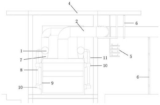
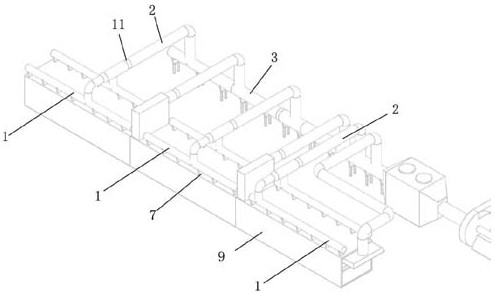
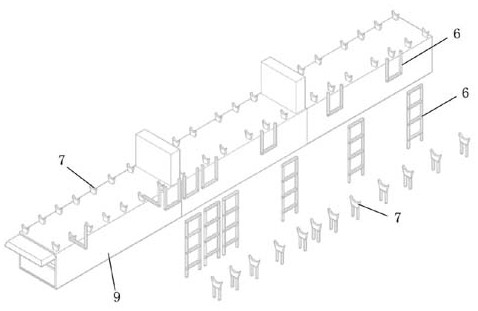
[0037] Such as Figure 1~Figure 6 As shown, a method for installing an aluminized pipeline in a drying furnace of a continuous annealing unit, including

[0038] Step 1. Optimized arrangement of pipelines and supports:

[0039] Step 1.1, use BIM three-dimensional modeling software to establish three-dimensional solid models of longitudinal branch pipe 1, horizontal branch pipe 2, main pipe 3, process steel platform 4, and furnace shell 9 according to the pipeline construction design drawing to construct a model space close to the actual site; in the model space Optimize the layout of pipelines, analyze and observe the interference between the smoke exhaust aluminized pipeline and the process steel platform 4, and the cable tray 5, and control the elevation of the pipeline within a relatively concentrated range to reserve installation space for the arrangement of the cable tray 5;

[0040] Step ...


PUM


Abstract

Specifically, the invention is a method for installing an aluminized pipeline in a drying furnace of a continuous annealing unit; it is characterized in that it includes step 1, optimizing the arrangement of pipelines and supports; step 2, prefabricating the pipeline in sections; and step 3, welding and installing the pipeline. This method optimizes the arrangement of pipelines and supports through BIM technology, determines the best direction of pipelines, and accurately locates the position of supports. Utilize the parameterization feature of the pipeline model to prefabricate the pipeline in sections and then carry out aluminizing treatment. When welding the pipeline, the welding rod variety is selected, the positioning tool is made for the pipeline assembly, and the pipeline is welded by the single-sided welding and double-sided forming process. A series of protective measures are taken during pipeline installation to ensure that the aluminized layer of the pipeline is not damaged. This installation method reduces the difficulty of installing the aluminized pipeline and speeds up the construction progress. As an advanced technology in the field of pipeline installation, it effectively solves the key technical problems of aluminized pipeline construction.

Description

technical field [0001] The invention relates to the field of metallurgical engineering pipeline installation, in particular to a method for installing an aluminized pipeline in a drying furnace of a continuous annealing unit. Background technique [0002] In the installation of aluminized pipes in the drying furnace of the cold-rolled horizontal continuous annealing unit, in order to save material costs and reduce project costs, carbon steel pipes are generally used for the installation of smoke exhaust pipes after aluminized treatment, and the aluminized layer of carbon steel aluminized pipes Performance indicators such as high temperature resistance, oxidation resistance, and corrosion resistance are close to those of stainless steel. Generally, the traditional pipeline installation method adopts the method of purchasing finished steel pipes and directly aluminizing them to the site for piping construction. Because the material of ordinary carbon steel pipes changes after ...

Claims


Application Information

Patent Timeline
Patent Type & Authority Patents(China)
IPC IPC(8): B23P15/00
CPCB23P15/00
Inventor 黄轶宋文智洪陈超陈兆兴
Owner SHANGHAI ERSHIYE CONSTR CO LTD
Why Eureka
Try Eureka