Supercharge Your Innovation With Domain-Expert AI Agents!

Four-shaft mechanical arm

A robotic arm and shaft arm technology, applied in the field of robotics, can solve the problems of increased load, increased weight of the robotic arm, and low accuracy of the robotic arm, and achieves the effect of lowering the center of gravity, rational structure, and improving movement accuracy

Pending Publication Date: 2020-01-17
深圳市智能机器人研究院
View PDF0 Cites 0 Cited by
  • Summary
  • Abstract
  • Description
  • Claims
  • Application Information

AI Technical Summary

Problems solved by technology

[0003] On the one hand, each joint of the teaching robot directly drives the mechanical arm to swing and rotate through the steering gear. Since the steering gear is installed at the rotation of each joint, this will increase the weight of the mechanical arm
The load on the steering gear driving the first axis is increased, resulting in a very small load capacity at the end of the mechanical arm, and the positioning accuracy of the steering gear is low
The connecting rod mechanism driven by the steering gear cannot rotate backwards, and there is a dead point in the rotatable space range, which makes the robot arm unable to reach the specified space position, resulting in low precision of the robot arm and limited range of motion
[0004] On the other hand, the second, third, and fourth axes of the robot arm are driven by the connecting rod mechanism driven by the steering gear installed on both sides of the robot arm, which will result in no separate drive structure for the fourth axis of the robot arm to move independently. It does not conform to the form that all joints of the robotic arm on the market can move independently, and at the same time, the fourth-axis robotic arm cannot fully reach the designated position, resulting in poor precision of the robotic arm

Method used


Image

  • Four-shaft mechanical arm
  • Four-shaft mechanical arm
  • Four-shaft mechanical arm

Examples


Embodiment Construction

[0025] Combine below Figure 1 to Figure 6 The present invention is further described.

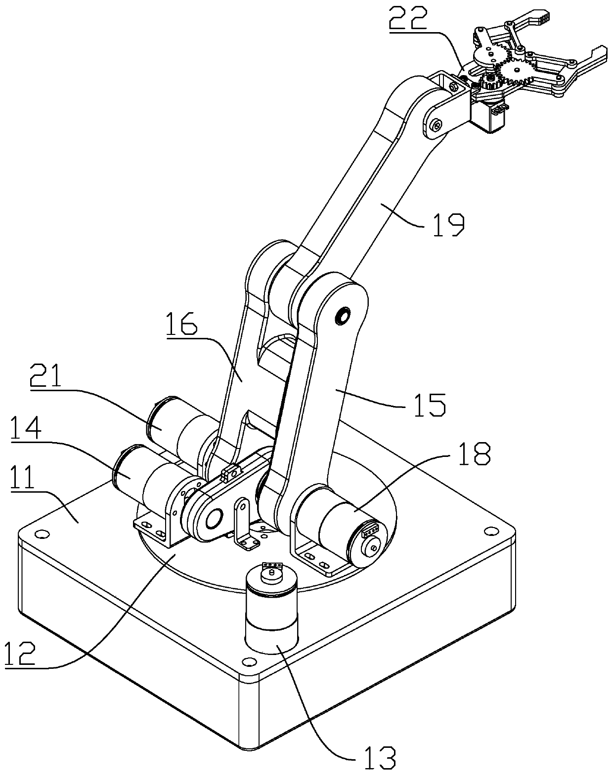
[0026] The present invention relates to a four-axis mechanical arm, which includes a base 11, a one-axis assembly, a two-axis assembly, a three-axis assembly and a four-axis assembly.

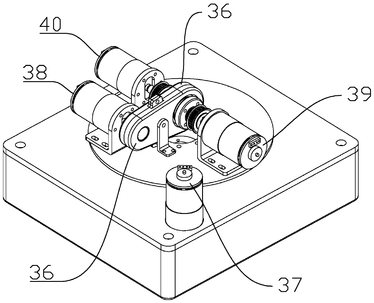
[0027] The one-axis assembly is installed on the base 11, and the one-axis assembly includes a one-axis turntable 12 and one-axis driver 13, and the one-axis driver 13 selects a motor, and the one-axis driver 13 drives the one-axis turntable 12 to rotate, and the one-axis driver 13 passes through a toothed belt or a flat The belt drives the one-axis turntable 12 .

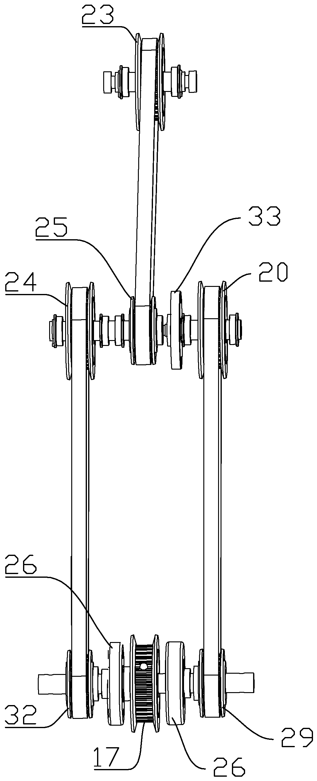
[0028] The two-axis assembly includes a two-axis driver 14, a two-axis one arm 15, a two-axis two arms 16 and a two-axis driven wheel 17. The two-axis driver 14 selects a motor, and the two-axis driver 14 is installed on the one-axis turntable 12. The two ends of two shafts and one arm 15 are respectively two and three input ends and two and t...


PUM


Abstract

The invention discloses a four-shaft mechanical arm. The mechanical arm comprises a base, a first shaft assembly, a second shaft assembly, a third shaft assembly and a fourth shaft assembly. The firstshaft assembly is arranged on the base and comprises a first shaft rotating disc and a first shaft driver; the second shaft assembly comprises a second shaft driver, a second shaft first arm, a second shaft second arm and a second shaft driven wheel, the third shaft assembly comprises a third shaft driver, a third shaft arm, and a third shaft driven wheel, the fourth shaft assembly comprises a fourth shaft driver, a fourth shaft arm and a fourth shaft driven wheel, the second shaft driver, the third shaft driver and the fourth shaft driver are arranged on a first shaft rotating disc, the gravity centre of the four-shaft mechanical arm is reduced, and the weight of the second shaft first arm, the second shaft second arm, the third shaft arm and the fourth shaft arm can be reduced; the first shaft driver drives the first shaft rotating disc, the second shaft driver drives the second shaft first arm and the second shaft second arm, the third shaft driver drives the third shaft arm, the fourth shaft driver drives the fourth shaft arm, all joints independently move, and the moving precision of the four-shaft mechanical arm is improved. The mechanical arm is reasonable in structure andcan be widely applied to the technical field of robots.

Description

technical field [0001] The invention relates to the technical field of robots, in particular to a four-axis mechanical arm. Background technique [0002] At present, most of the manipulator structures are four-axis manipulators that drive the manipulator to rotate by directly driving the steering gear or the steering gear driving the linkage mechanism at each joint. Although these mechanisms reduce the complexity of the mechanical structure and reduce the mechanical Arm cost, but there are many disadvantages: [0003] On the one hand, each joint of the teaching robot directly drives the mechanical arm to swing and rotate through the steering gear. Since the steering gear is installed at the rotation of each joint, this will increase the weight of the mechanical arm. The increased load on the servo that drives the first axis results in a very small load capacity at the end of the arm and low positioning accuracy of the servo. The connecting rod mechanism driven by the steer...

Claims


Application Information

Patent Timeline
IPC IPC(8): B25J18/00
CPCB25J18/00
Inventor 都晓锋张启毅马宠涵吕志博席宁
Owner 深圳市智能机器人研究院
Features
  • R&D
  • Intellectual Property
  • Life Sciences
  • Materials
  • Tech Scout
  • Unparalleled Data Quality
  • Higher Quality Content
  • 60% Fewer Hallucinations
Learn More