Conveying device penetrating through fireproof roller shutter door and having torsion limiting function

A technology of torque limiting and conveying equipment, applied in the directions of transportation, packaging, roller table, etc., can solve problems such as failure safety, falling on the ground or under fire shutter doors, hidden dangers, etc., to achieve the effect of improving safety performance

Pending Publication Date: 2020-01-17
SUZHOU HONGAN MACHINERY
View PDF0 Cites 0 Cited by
  • Summary
  • Abstract
  • Description
  • Claims
  • Application Information

AI Technical Summary

Problems solved by technology

[0004] At present, many logistics transportation systems inevitably pass through fire shutter doors. The traditional method is to directly disconnect the conveying equipment, that is, to set up two independent conveyors on both sides of the fire shutter door area (conveyors usually include motors and driven by motors). Several conveying rollers), leaving the width of the fire shutter in between, but this method will cause the material to fall off the conveyor and fall to the ground or under the fire shutter door when conveying small materials or double-track shutter doors, causing failure and Potential safety hazard, so it needs to be improved urgently

Method used


Image

  • Conveying device penetrating through fireproof roller shutter door and having torsion limiting function
  • Conveying device penetrating through fireproof roller shutter door and having torsion limiting function
  • Conveying device penetrating through fireproof roller shutter door and having torsion limiting function

Examples


Embodiment Construction

[0028] In order to describe the technical content, structural features, goals and effects of the present invention in detail, the following examples are given to describe the embodiments in conjunction with the accompanying drawings.

[0029] In describing the present invention, it is to be understood that the terms "central", "longitudinal", "transverse", "front", "rear", "left", "right", "vertical", "horizontal", The orientations or positional relationships indicated by "top", "bottom", "inner", "outer", etc. are based on the orientations or positional relationships shown in the drawings, and are only for the convenience of describing the present invention and simplifying the description, rather than indicating or implying The devices or elements referred to must have a specific orientation, be constructed and operate in a specific orientation, and therefore should not be construed as limiting the scope of the invention.

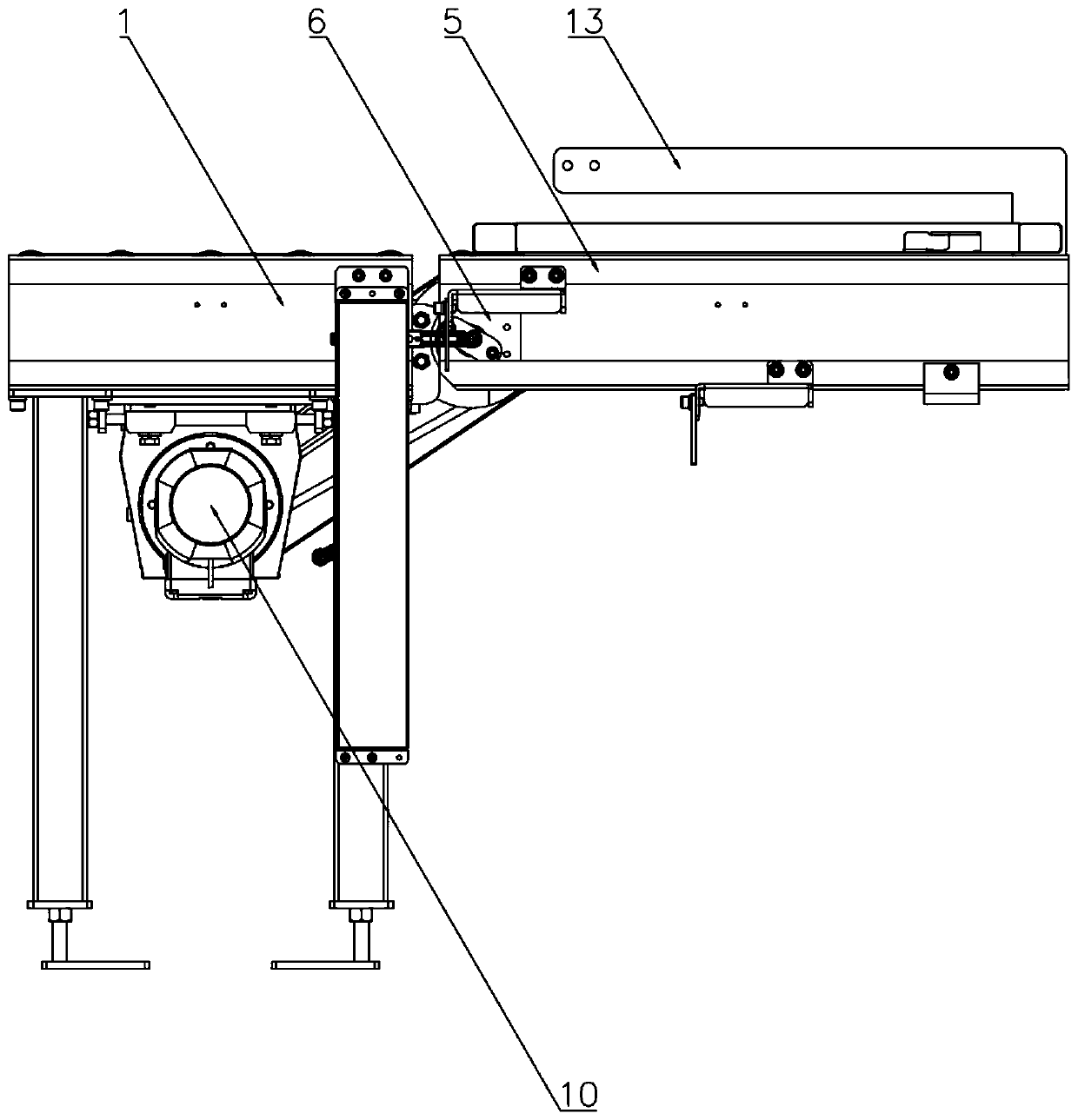
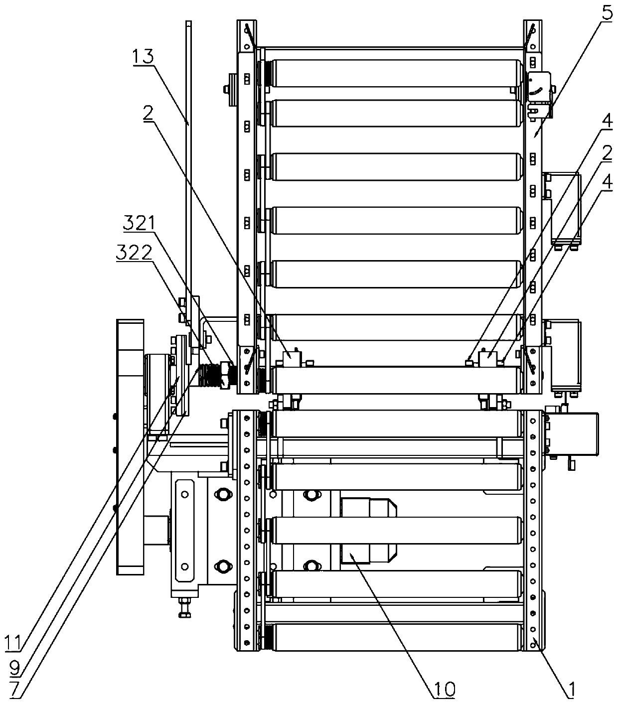
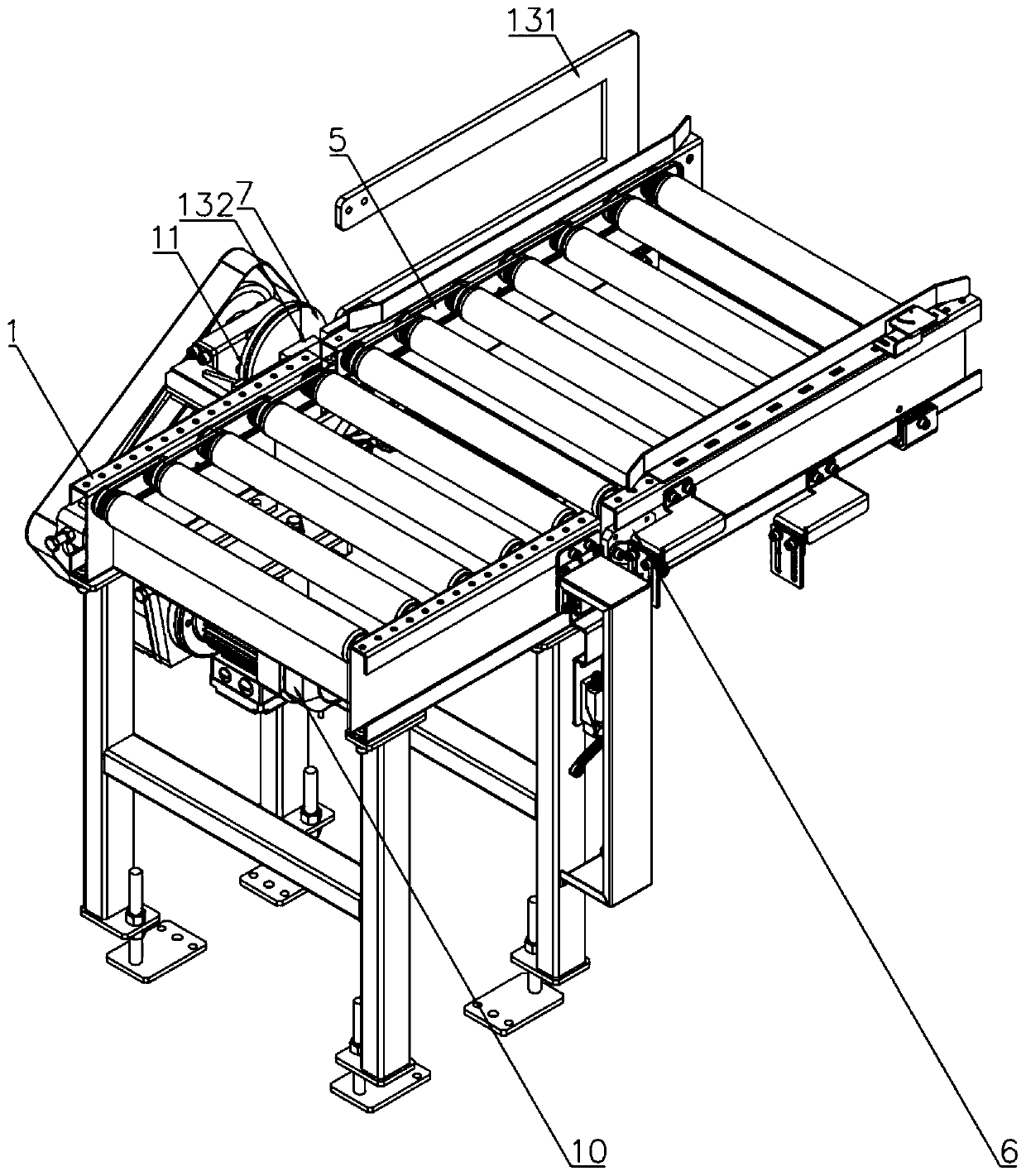
[0030] The present invention provides a conveying de...


PUM


Abstract

The invention provides a conveying device penetrating through a fireproof roller shutter door and having a torsion limiting function. The conveying device comprises a fixed conveyor, wherein the fixedconveyor is connected with a bearing seat; the bearing seat is connected with a rotating shaft; the rotating shaft is provided with a locking groove; the rotating shaft is provided with a locking piece at the locking groove; the rotating shaft comprises a transmission part and a torsion limiting part; the two ends of the transmission part are connected with turnover frames; a turnover conveyor isarranged between the two turnover frames; fixing pieces are arranged between the turnover frames and the transmission part; the torsion limiting part comprises an external thread section; the external thread section is connected with an adjusting nut; the torsion limiting part further comprises a sliding section; the sliding section is connected with a driven clutch disc; a compression spring isarranged between the driven clutch disc and the adjusting nut; the sliding section is provided with a shaft end baffle; the fixed conveyor is connected with a motor, the motor is connected with a driving clutch disc; the driving clutch disc and the driven clutch disc are coaxially arranged; steel balls are embedded in the abutting surface of the driving clutch disc; the driven clutch disc is provided with a torsion limiting groove; and the turnover conveyor is connected with a manual separation mechanism. The conveying device has the functions of conveying materials by penetrating through thefireproof roller shutter door and limiting and protecting torsion.

Description

technical field [0001] The invention relates to the field of logistics conveying equipment, in particular to a conveying equipment that passes through a fireproof rolling door and has a torque limiting function. Background technique [0002] The concept of logistics originated in the 1930s and originally meant "physical distribution" or "goods distribution". China's logistics terminology standard defines logistics as: logistics refers to the organic combination of transportation, storage, loading and unloading, packaging, distribution processing, distribution, information processing and other functions according to actual needs during the physical flow of goods from the supply point to the receiving point The process of realizing the user's requirements. [0003] With the increase of the volume of logistics transportation, the logistics transportation system that needs to be matched also presents a trend of three-dimensional, intelligent and complex, and the fire protection...

Claims


Application Information

Patent Timeline
IPC IPC(8): B65G13/00B65G13/11
CPCB65G13/00B65G13/11
Inventor 田丹丹
Owner SUZHOU HONGAN MACHINERY
Why Eureka
Try Eureka