
Rapid construction method of cantilever continuous beam

A construction method and fast technology, applied in the direction of bridges, bridge construction, erection/assembly of bridges, etc., can solve the problems of elongated construction period, waste of construction force, and unreasonable use of construction force, so as to optimize the connection between processes and improve work efficiency. efficiency effect

Inactive Publication Date: 2020-01-17
CHINA RAILWAY 14TH CONSTR BUREAU GRP 4TH ENG
View PDF5 Cites 4 Cited by
  • Summary
  • Abstract
  • Description
  • Claims
  • Application Information

AI Technical Summary

Benefits of technology

This patented innovation allows for quicker and more efficient connections during building processes that require heavy equipment like cranes. It achieves this through utilizing specialized materials called sturdy timber frames (SBS) instead of traditional forms made from wood. These SBS are designed with specific strength characteristics to support loads while also being lighter than regular wooden templates. They may have different shapes depending upon their intended purpose. Additionally, they provide easy access when needed without having to remove them altogether. Overall, these improvements enhance the performance of buildings' manufacturing process.

Problems solved by technology

This patented describes how suspension bridge constructions were traditionally time-consuming due to their fixed length. However, there has been an improvement over these methods by allowing them more flexibility with respect to crossing obstructions or maneuverable paths through obstacles like rocks.

Method used


Image

  • Rapid construction method of cantilever continuous beam
  • Rapid construction method of cantilever continuous beam
  • Rapid construction method of cantilever continuous beam

Examples


Embodiment Construction

[0065] In order to make the purpose, features and advantages of the present invention more obvious and understandable, the technical solutions protected by the present invention will be clearly and completely described below using specific embodiments and accompanying drawings. Obviously, the implementation described below Examples are only some embodiments of the present invention, but not all embodiments. Based on the embodiments in this patent, all other embodiments obtained by persons of ordinary skill in the art without creative efforts fall within the protection scope of this patent.

[0066] It will be understood that when an element or layer is referred to as being "on," "connected" or "coupled" to another element or layer, it may be directly on, connected to, or directly on the other element or layer. Or coupled to said another element or layer, intervening elements or layers may also be present. In contrast, when an element is referred to as being "directly on," "di...


PUM


Abstract

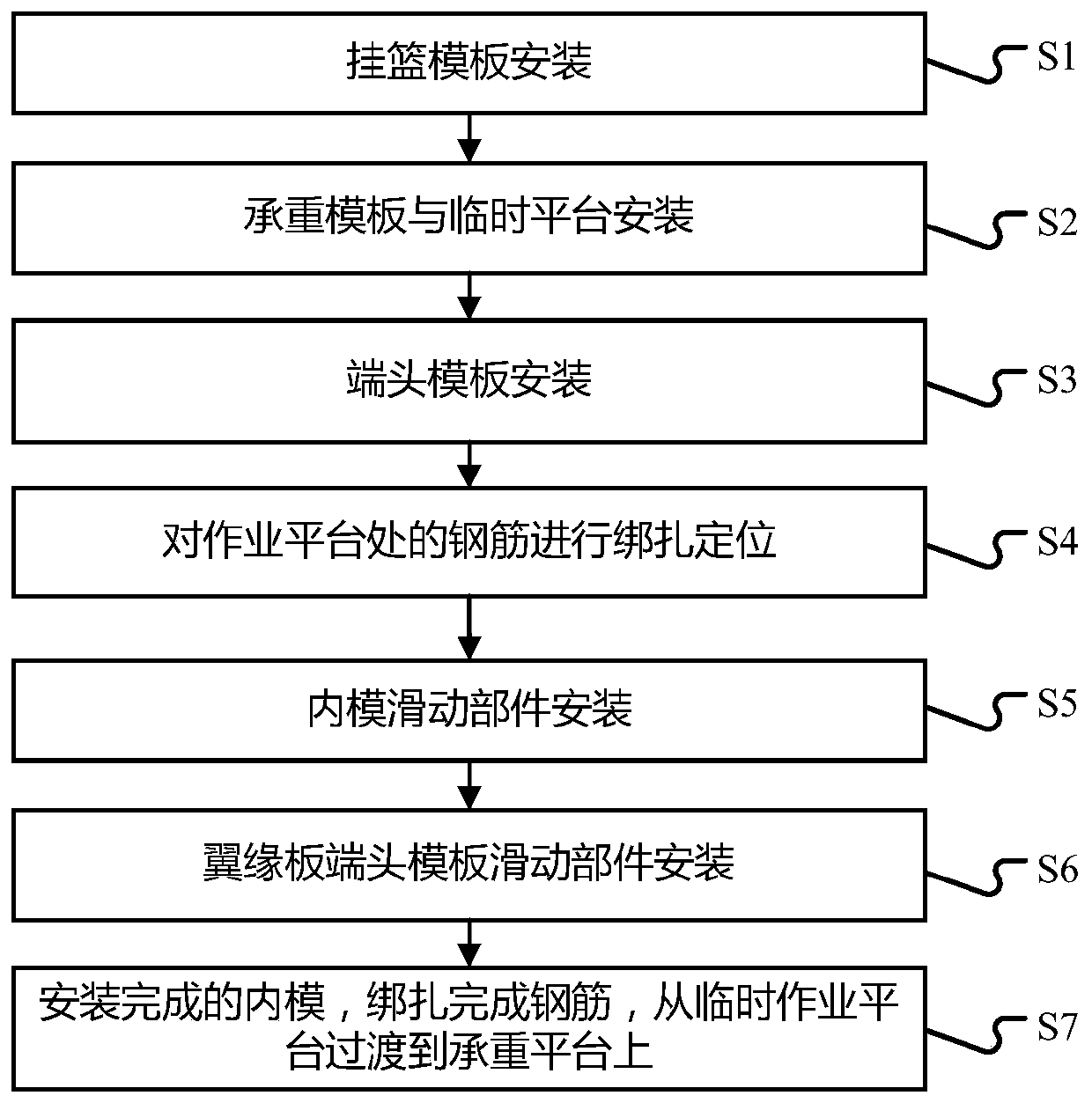
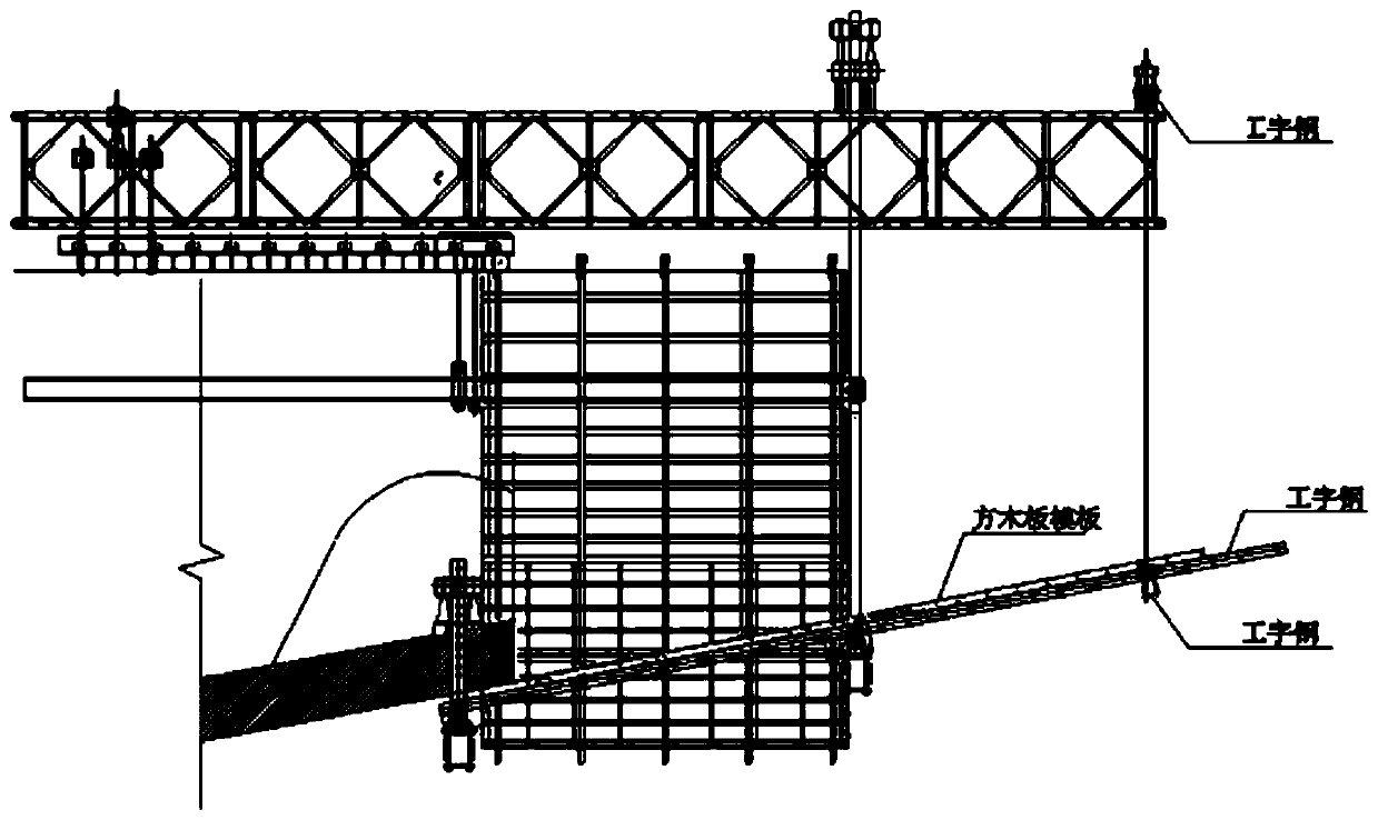
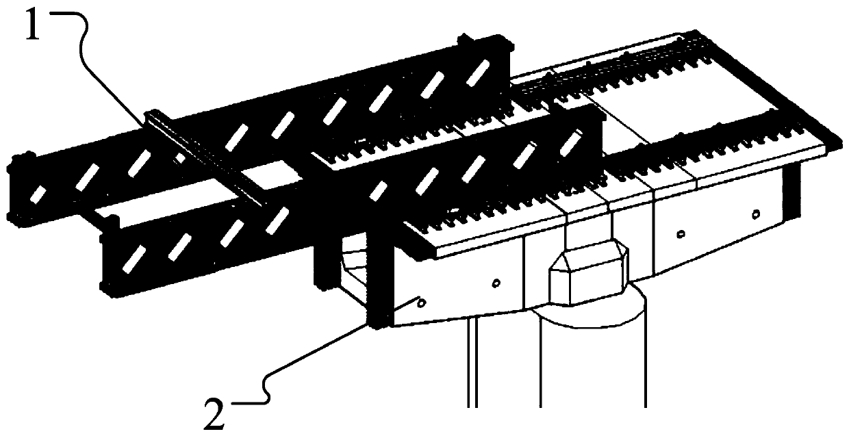
The invention provides a rapid construction method for a cantilever continuous beam. The rapid construction method comprises the steps that a hanging basket formwork is installed; a bearing formwork and a temporary platform are installed; an end template is installed; reinforcing steel bars at an operation platform are bound and positioned; an inner mold sliding part is installed; flange plate endtemplate sliding parts are installed; and the mounted inner mold and the bound reinforcing steel bars are transited to the bearing platform from the temporary operation platform. The equal-strength time of stage block concrete is fully utilized, the equal-strength time of the concrete is fully utilized to implement a next stage block template, reinforcing steel bars, prestress and the like by erecting a temporary platform, adjusting the construction procedures of reinforcing steel bar binding, prestress mounting, template mounting and the like, and the working efficiency is improved. The temporary operation platform can adopt a form of independently arranging a cantilever platform, can also adopt a construction operation platform mounted on an existing hanging basket, adopts a bailey beamas a main bearing structure, and adopts I-shaped steel as a simple and convenient operation platform so as to facilitate the mounting of reinforcing steel bars.

Description


Claims


Application Information

Patent Timeline
Owner CHINA RAILWAY 14TH CONSTR BUREAU GRP 4TH ENG
Learn More