
Self-dedusting road reflector based on sound wave vibration

A sonic vibration, self-dusting technology, applied in the direction of roads, roads, road signs, etc., can solve the problems of affecting the adsorption effect, easy to scratch the mirror surface, unable to absorb dust, etc.

Inactive Publication Date: 2020-01-17
张斌
View PDF1 Cites 9 Cited by
  • Summary
  • Abstract
  • Description
  • Claims
  • Application Information

AI Technical Summary

Problems solved by technology

[0005] The above solution adopts the wind wheel to drive the static ring to generate static electricity by rotating and frictionally generating static electricity to absorb the dust raised by the vehicle and adhered to the mirror surface. Although it solves the problem that manual erasing of dust is difficult and the mirror surface is easy to scratch in the prior art , but there are still the following deficiencies:
[0006] First, the scheme uses a wind wheel to drive the static ring to rotate. However, the wind wheel can only use wind energy to generate power when the wind blows. In some areas with low wind and less wind, it is difficult for the wind wheel to use wind energy. Drive the electrostatic ring to rotate, and the electrostatic ring cannot generate enough static electricity, resulting in insignificant dust removal effect of this solution
[0007] Second, when the electrostatic ring is used for a long time, more and more dust will gradually be adsorbed on its surface, which will affect the adsorption effect, making it unable to continue to adsorb dust in the air and on the mirror surface

Method used


Image

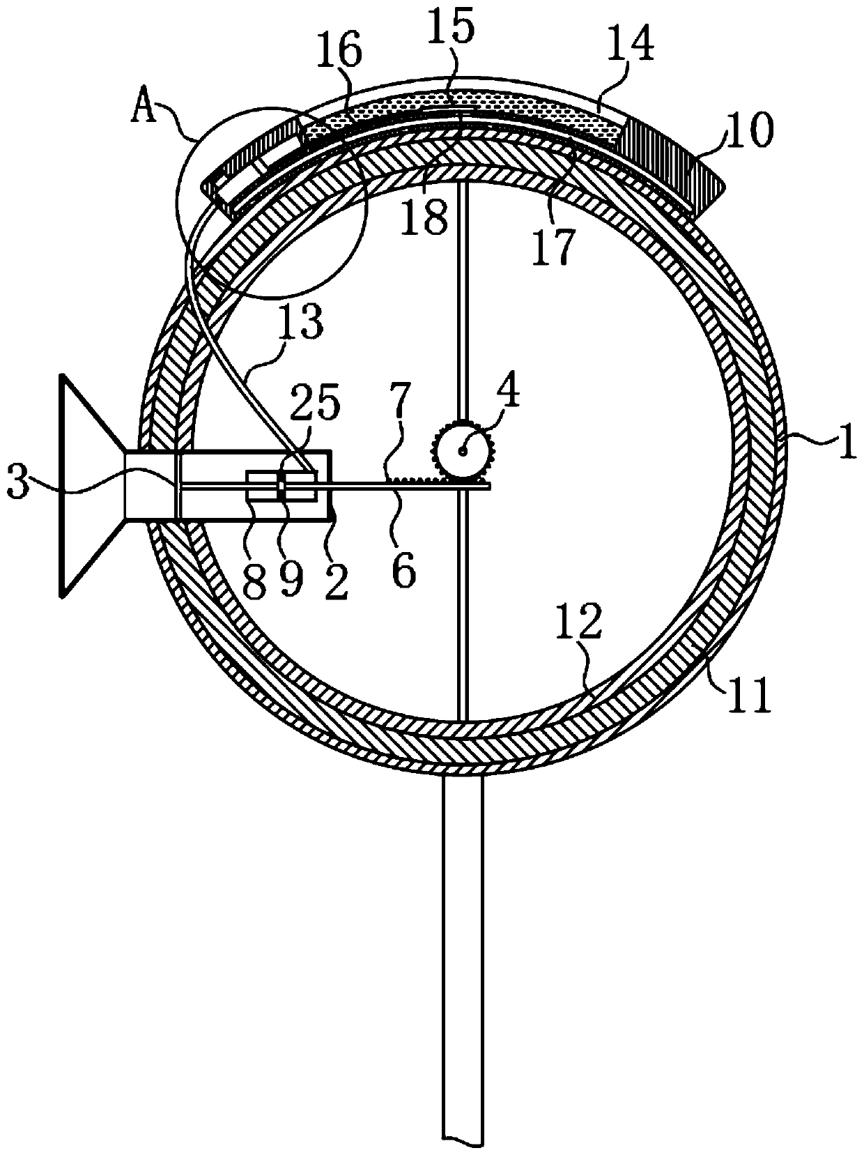
  • Self-dedusting road reflector based on sound wave vibration
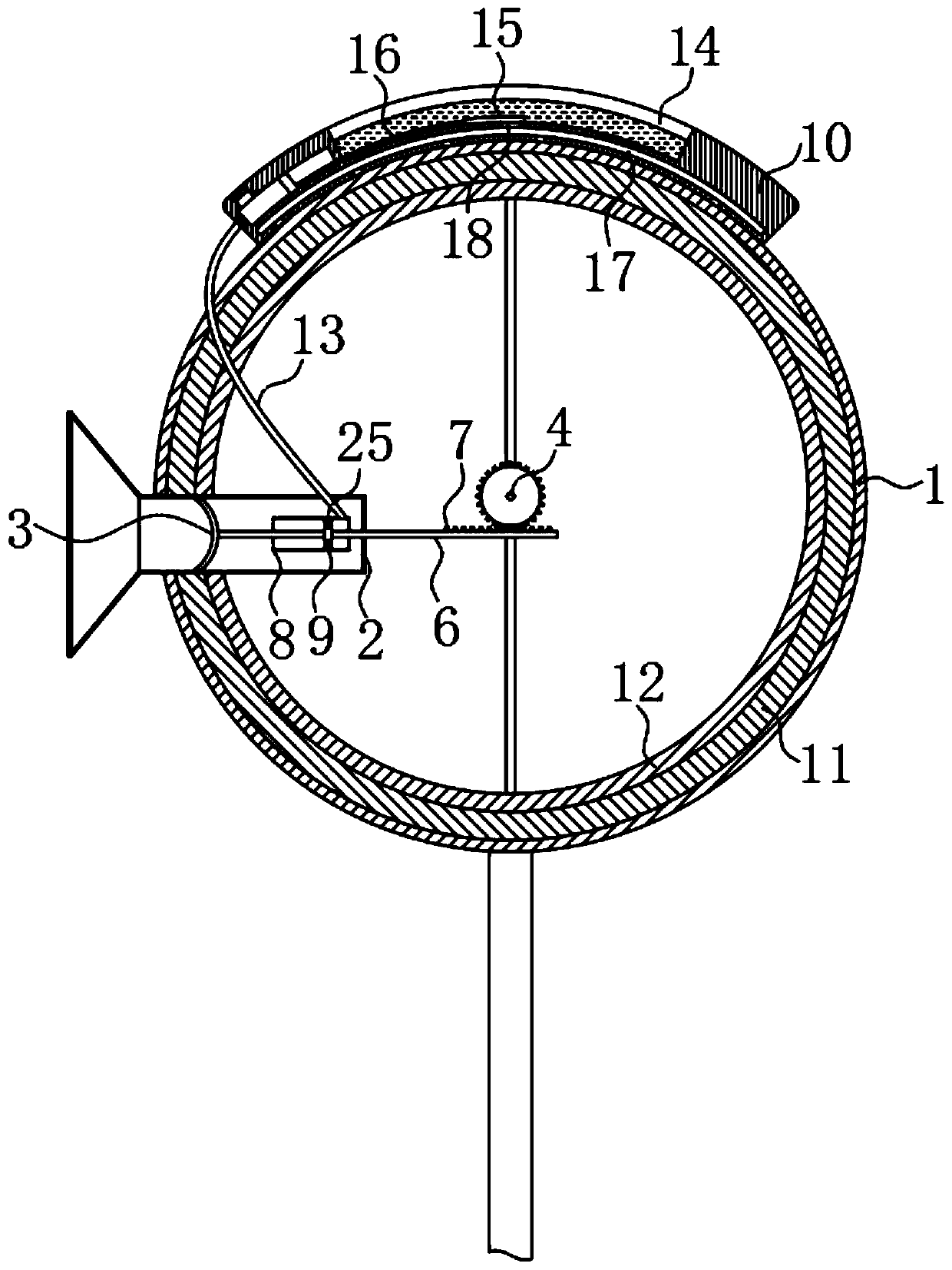
  • Self-dedusting road reflector based on sound wave vibration
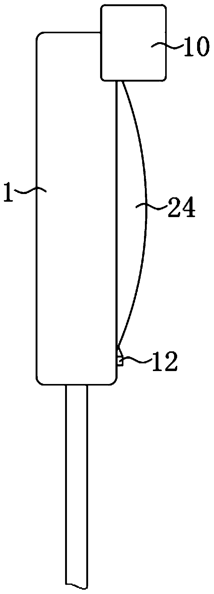
  • Self-dedusting road reflector based on sound wave vibration

Examples


Embodiment Construction

[0026] The following will clearly and completely describe the technical solutions in the embodiments of the present invention with reference to the accompanying drawings in the embodiments of the present invention. Obviously, the described embodiments are only some, not all, embodiments of the present invention.

[0027] In describing the present invention, it should be understood that the terms "upper", "lower", "front", "rear", "left", "right", "top", "bottom", "inner", " The orientation or positional relationship indicated by "outside", etc. is based on the orientation or positional relationship shown in the drawings, and is only for the convenience of describing the present invention and simplifying the description, rather than indicating or implying that the referred device or element must have a specific orientation, so as to Specific orientation configurations and operations, therefore, are not to be construed as limitations on the invention.

[0028] refer to Figure ...


PUM


Abstract

The invention discloses a self-dedusting road reflector based on sound wave vibration. The self-dedusting road reflector comprises a shell with a circular section, a circular opening is coaxially formed in one side of the shell, a mirror surface is arranged at the opening of the shell, an arc-shaped rain shielding plate is installed at the upper end of the shell, a sound gathering cover is arranged on the side wall of the shell in a penetrating mode, and a vibration piece with the vibration direction being the horizontal direction is fixedly connected to the inner wall of the sound gathering cover. According to the invention, the vibration sheet, the sound gathering cover, a dust adsorption mechanism, a first driving mechanism, a second driving mechanism and a pushing mechanism are arranged; the vibration sheet can vibrate by utilizing sound waves of automobile whistling sound and engine sound; the movable friction ring is driven to rotate to rub the fixed friction ring to generate static electricity, dust raised by an automobile is adsorbed, water in the water storage tank can be sprayed out through the spraying holes after the automobile passes through the reflector many times, dust on the movable friction ring and the mirror surface is flushed, and the follow-up adsorption effect of the movable friction ring is prevented from becoming poor.

Description

technical field [0001] The invention relates to the technical field of road facilities, in particular to a self-dusting road reflector based on sound wave vibration. Background technique [0002] The corners of the road are generally equipped with road reflectors. The road reflectors are used to help the driver grasp the situation of the oncoming vehicle, so as to ensure that the driver has enough time to make corresponding driving operations, thereby greatly reducing the occurrence of traffic accidents at the turn. Rate. [0003] However, the road reflector is set on the side of the road, and a large amount of dust will be raised when the vehicle passes by. The dust is easy to adhere to the mirror surface of the reflector, resulting in poor reflection effect of the road reflector, which affects the driver's observation of the oncoming vehicle situation, increase the probability of traffic accidents; and because the mirror surface of the reflector is convex and has a certai...

Claims


Application Information

Patent Timeline
Patent Type & Authority Applications(China)
IPC IPC(8): E01F9/619
CPCE01F9/619
Inventor 张斌
Owner 张斌
Learn More