
Real-time Monitoring Method of Tunnel Deformation Based on Millimeter Wave Radar

A millimeter-wave radar and real-time monitoring technology, applied in radio wave measurement systems, radio wave reflection/re-radiation, measurement devices, etc., can solve the problems of difficult real-time monitoring, large amount of scanning and processing data, and hours spent

Active Publication Date: 2020-12-11
CCCC SECOND HARBOR ENG +2
View PDF1 Cites 0 Cited by
  • Summary
  • Abstract
  • Description
  • Claims
  • Application Information

AI Technical Summary

Problems solved by technology

The use of 3D laser scanning can quickly carry out non-contact measurement, and at the same time can carry out tunnel monitoring measurement to realize the function of dynamic monitoring. However, due to the influence of smoke, dust, noise, etc. in the tunnel, the measurement accuracy of 3D laser scanning cannot be guaranteed, and the scanning process The amount of data is too large, and sometimes it takes several hours to scan data transmission and processing, which cannot truly realize the real-time monitoring and early warning function of the tunnel
Therefore, in order to solve the problem of tunnel settlement and convergence deformation monitoring in harsh construction environments, a device and method with high penetrating power, high precision, and long-term and automatic monitoring are needed to solve the real-time monitoring that is difficult to achieve in the existing traditional measurement problems, realize high-precision collection of tunnel deformation data, real-time monitoring and early warning, provide timely deformation evidence for tunnel construction, and ensure tunnel construction safety

Method used


Image

  • Real-time Monitoring Method of Tunnel Deformation Based on Millimeter Wave Radar
  • Real-time Monitoring Method of Tunnel Deformation Based on Millimeter Wave Radar
  • Real-time Monitoring Method of Tunnel Deformation Based on Millimeter Wave Radar

Examples


Embodiment Construction

[0033] The present invention will be further described in detail below in conjunction with the accompanying drawings, so that those skilled in the art can implement it with reference to the description.

[0034] It should be noted that the experimental methods described in the following embodiments, unless otherwise specified, are conventional methods, and the reagents and materials, if not otherwise specified, can be obtained from commercial sources; in the description of the present invention, The terms "landscape", "portrait", "top", "bottom", "front", "rear", "left", "right", "vertical", "horizontal", "top", "bottom", The orientation or positional relationship indicated by "inner", "outer", etc. is based on the orientation or positional relationship shown in the drawings, which is only for the convenience of describing the present invention and simplifying the description, and does not indicate or imply that the referred device or element must have Certain orientations, co...


PUM


Abstract

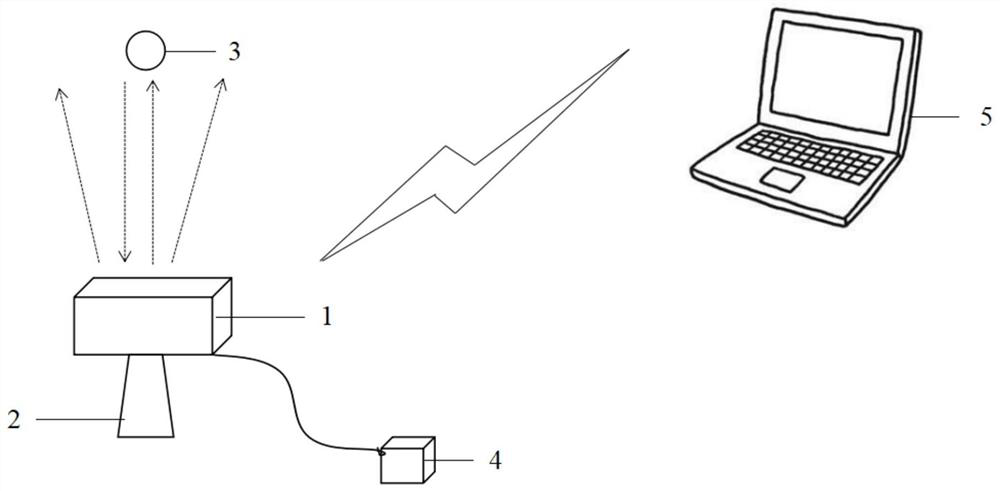
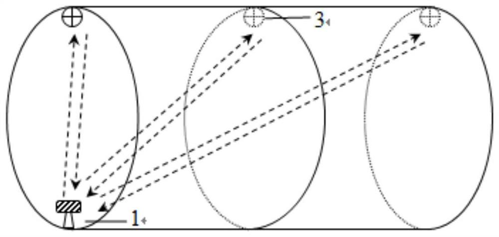
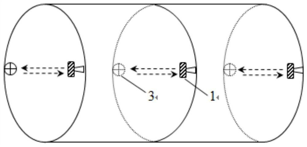
The invention discloses a tunnel deformation real-time monitoring method based on millimeter-wave radars. The method includes the following steps of firstly, dividing sections, wherein a to-be-monitored section of a tunnel is divided into a section 1, a second 2 and the like until a section N, and each section is provided with a plurality of monitoring fracture surfaces; secondly, arranging radarbeacons, wherein the top of each monitoring fracture surface is provided with one vertical radar beacon, and each horizontal surface is provided with two opposite horizontal radar beacons; thirdly, arranging the radars, wherein the bottom of each section is provided with one vertical radar and meanwhile provided with one horizontal radar or a pair of opposite horizontal radars; and fourthly, conducting monitoring, wherein each vertical radar and each horizontal radar are connected with data collecting and transmitting instruments, the data collecting and transmitting instruments are wirelesslyconnected with a working station, the working station analyzes the radar monitoring data, and therefore the vault vertical displacement and clearance convergence value on each monitoring fracture surface are obtained. By means of the phase interferometry technology of the millimeter-wave radars, the real-time monitoring of settlement and convergence data of each fracture surface can be conveniently and rapidly realized.

Description

technical field [0001] The invention relates to the field of tunnel deformation monitoring. More specifically, the present invention relates to a real-time monitoring method for tunnel deformation based on millimeter wave radar. Background technique [0002] During the construction of mountain tunnels or shield tunnels, total stations are usually used for tunnel deformation monitoring, but the real-time deformation monitoring function of tunnels cannot be realized by using total stations. Influences such as manual reading errors. In view of the above shortcomings, in recent years, some people have gradually begun to try out the tunnel 3D laser scanning technology, and simultaneously developed a corresponding data processing platform, such as patent CN106930784A. The use of 3D laser scanning can quickly carry out non-contact measurement, and at the same time can carry out tunnel monitoring measurement to realize the function of dynamic monitoring. However, due to the influe...

Claims


Application Information

Patent Timeline
Patent Type & Authority Patents(China)
IPC IPC(8): E21F17/18G01S13/88G01B15/06F16M11/04
CPCE21F17/18E21F17/185F16M11/04G01B15/06G01S13/886
Inventor 翟世鸿吴忠仕陈培帅江鸿唐湘隆冯德定袁青袁远何志军沈学军林玉刚杨林刘毅王伟梁晓腾闫鑫雨黄威杨擎蒋道东高如超孔茜许超熊栋栋邱敏贺创波方俊周勇刘鑫幸元野
Owner CCCC SECOND HARBOR ENG
Learn More