Condenser microphone

a condenser microphone and microphone technology, applied in the field of electroacoustic transducers, can solve problems such as resonance in the audio frequency range, and achieve the effects of improving the ability of the condenser microphone to withstand dripping water, and improving the environmental adaptability of the condenser microphon

Inactive Publication Date: 2008-09-11
YAMAHA CORP
View PDF3 Cites 52 Cited by
  • Summary
  • Abstract
  • Description
  • Claims
  • Application Information

AI Technical Summary

Benefits of technology

[0013]It is preferable that the first sound hole of the first plate does not overlap with the second sound hole of the second plate in plan view since dust, light, and liquid drops cannot directly enter into the package even when they pass through both of the first hole of the first plate and the second hole of the second plate. This improves the environmental adaptability of the condenser microphone.
[0014]It is possible to further include a porous sheet, which is inserted between the first plate and the second plate. The porous sheet further improves the environmental adaptability of the condenser microphone. In addition, it is possible to further include a water-repellant film, which is formed in the surrounding area of the sound hole in the backside of the plate positioned in proximity to the electroacoustic transducer die. This improves the drip-proof ability of the condenser microphone.
[0015]The periphery of the plate includes a projection area of the electroacoustic transducer die. Generally speaking, the electroacoustic transducer die of the condenser microphone has a relatively high output impedance, whereby the plate functions as a noise shield of the electroacoustic transducer die; hence, it is possible to improve the S / N ratio of the condenser microphone.
[0016]When the plate is set to the ground potential, it is possible to further improve the noise shield effect of the plate; hence, it possible to further improve the S / N ratio of the condenser microphone.
[0017]In a second aspect of the present invention, an electroacoustic transducer includes a condenser microphone, and an external wiring substrate which the condenser microphone joins. The condenser microphone further includes a bottom portion having a through-hole, which joins the external wiring substrate, a cover, which joins the bottom portion so as to form a cavity together with the bottom portion, a plate, which joins the bottom portion and which is thinner than the length of the through-hole, wherein the plate has a sound hole overlapping with the through-hole in plan view, and an electroacoustic transducer die, which further includes a fixed electrode and a diaphragm electrode, which are positioned opposite to each other, as well as a support for supporting and enclosing the fixed electrode and the diaphragm electrode, wherein the external wiring substrate has a second through-hole that overlaps with the through-hole of the bottom portion. Compared with the technology in which the sound hole is formed in the bottom portion of the package joining the external wiring substrate, it is possible to reduce the depth of the sound hole since the sound hole is formed in the plate whose thickness is smaller than the thickness of the bottom portion joining the external wiring substrate. This makes it possible to increase the resonance frequency of the sound hole.
[0018]In the above, the support joins the bottom portion or the plate in relation to the surrounding area of the sound hole of the plate. Since the sound hole overlaps with the electroacoustic transducer die in plan view, it is possible to reduce the size of a footprint of the condenser microphone; thus, it is possible to reduce the overall size of the electroacoustic transducer. Sound waves directly reach the electroacoustic transducer die from the bottom portion joining the external wiring substrate, whereby the external space having a relatively large volume, which lies externally of the electroacoustic transducer die within the package, can be used as a back cavity; thus, it is possible to reduce the cutoff frequency.

Problems solved by technology

There is a possibility in that dust, light, and liquid drops may enter into the sound hole so as to badly affect the operation of the electroacoustic transducer die within the package.
This unexpectedly causes resonance in the audio frequency range.

Method used


Image

  • Condenser microphone
  • Condenser microphone
  • Condenser microphone

Examples


Embodiment Construction

[0032]The present invention will be described in further detail by way of examples with reference to the accompanying drawings.

A. Preferred Embodiment

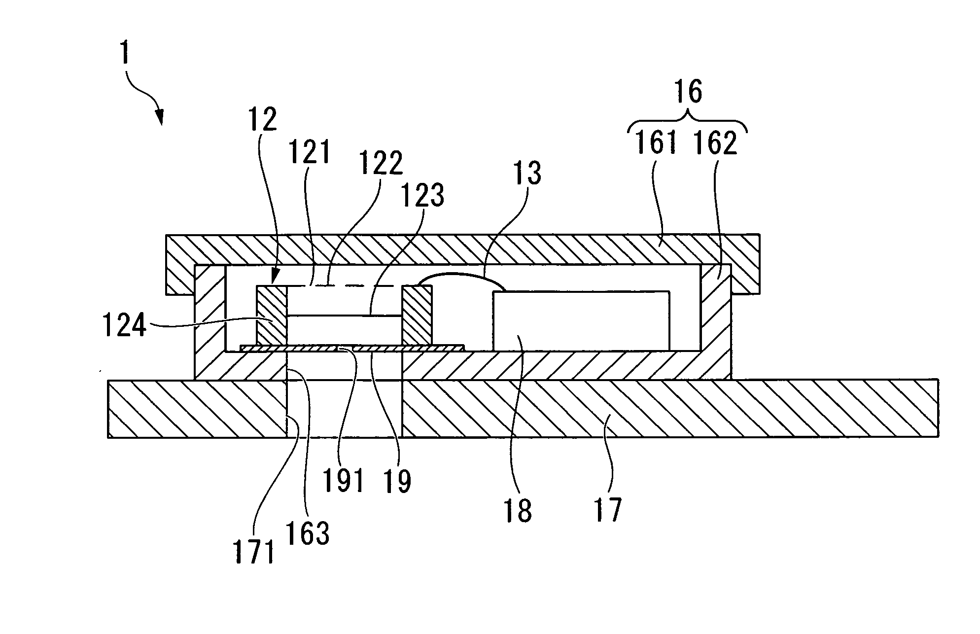
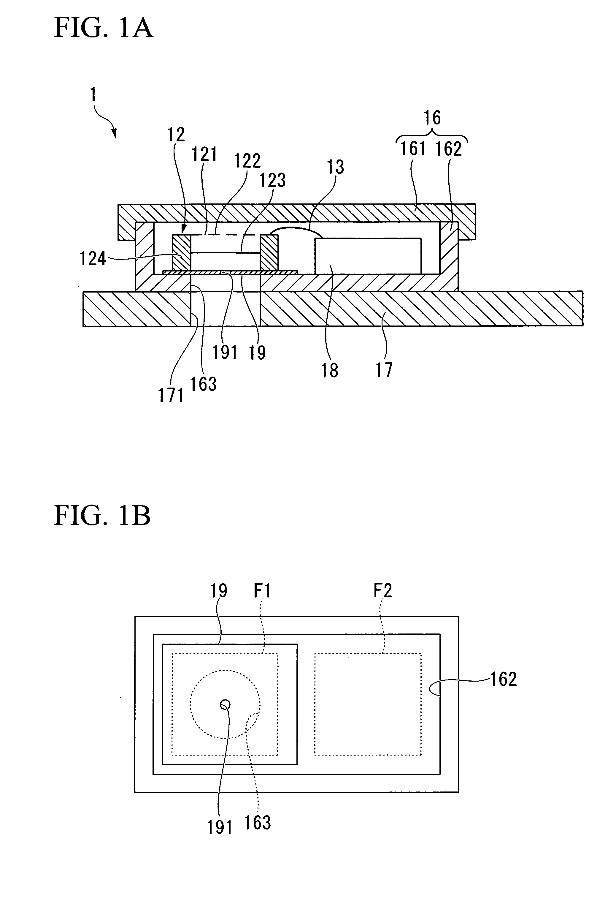
[0033]FIG. 1A is a longitudinal sectional view showing the essential parts of an electroacoustic transducer in accordance with a preferred embodiment of the present invention. The electroacoustic transducer including a condenser microphone 1 can be installed in various electronic devices such as portable telephone terminals, voice recorders, and notebook computers, in which it converts sounds into electric signals. A housing (or a casing) forming the exterior of the electroacoustic transducer incorporates an external wiring substrate 17 for mounting various electronic parts and components thereon. The condenser microphone 1 joins the external wiring substrate 17 via a ball grid array (BGA, not shown). A second through-hole 171 is formed to run through the external wiring substrate 17 at a prescribed position just below the condenser mi...


PUM


Abstract

An electroacoustic transducer includes a condenser microphone, which includes a package having a cavity and a through-hole, a plate whose thickness is thinner than the length of the through-hole and which has a sound hole overlapping with the through-hole in plan view, and an electroacoustic transducer die, which is stored in the cavity of the package. The electroacoustic transducer die includes a fixed electrode and a diaphragm electrode, which are positioned opposite to each other and which are supported by and enclosed inside of a support. The sound hole of the plate is reduced in dimensions realizing a small sectional area and a small depth, thus realizing a high resonance frequency higher than the audio frequency range.

Description

BACKGROUND OF THE INVENTION[0001]1. Field of the Invention[0002]The present invention relates to electroacoustic transducers including condenser microphones and in particular to condenser microphones encapsulated in packages suited to MEMS (Micro-Electro-Mechanical Systems).[0003]This application claims priority on Japanese Patent Application No. 2006-295057, the content of which is incorporated herein by reference.[0004]2. Description of the Related Art[0005]Conventionally-known condenser microphones are encapsulated in MEMS sensor packages. U.S. Patent Application Publication No. US 2005 / 0185812 A1 teaches a miniature silicon condenser microphone, in which an electroacoustic transducer die joining a wiring substrate is enclosed in a package having a cover and in which a sound hole allowing sound waves to reach the electroacoustic transducer die is formed in the cover of the package or the wiring substrate. There is a possibility in that dust, light, and liquid drops may enter into...

Claims


Application Information

Patent Timeline
Patent Type & Authority Applications(United States)
IPC IPC(8): H04R25/00
CPCH04R19/04H04R2499/11H01L2224/48091H01L2224/48137H01L2924/1461H01L2924/3025H01L2924/3011H01L2924/10253H01L2924/00014H01L2924/00
Inventor SATO, AKIYOSHI
Owner YAMAHA CORP
Why Eureka
Try Eureka