
Two-dimensional electrostatic scanning micromirror
A scanning micromirror and electrostatic technology, applied in optical components, optics, instruments, etc., can solve problems such as the inability to monitor two-dimensional scanning micromirrors in real time, achieve the effects of reducing stress and stiffness, improving accuracy, and improving reliability
- Summary
- Abstract
- Description
- Claims
- Application Information
AI Technical Summary
Problems solved by technology
Method used
Image

Examples
Embodiment 1
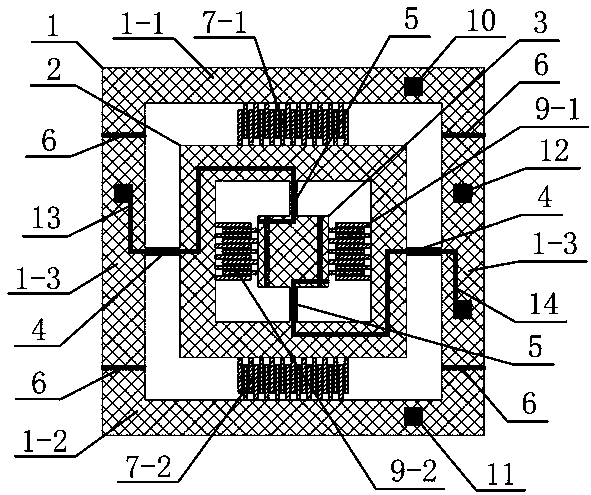
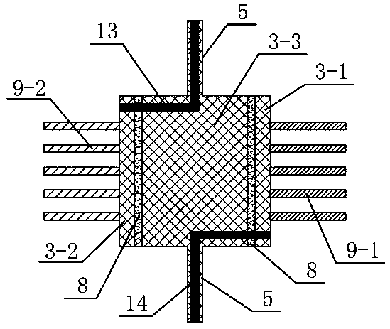
[0036] Such as figure 1 and figure 2 As shown, the two-dimensional electrostatic scanning micromirror of the present invention is based on silicon material and includes an outer frame 1, an inner frame 2 and a mirror surface 3, and the mirror surface 3 is square. The outer frame 1 and the inner frame 2 are connected together by two outer torsion beams 4, and the inner frame 2 and the mirror surface 3 are connected by two inner torsion beams 5, and the directions of the inner torsion beams 5 and the outer torsion beams 4 vertical. The mirror surface 3 can deflect around the inner torsion beam 5 as the axis, and the inner frame 2 and the mirror surface 3 can deflect around the outer torsion beam 4 as the axis, thereby realizing the deflection of the mirror surface 3 in two perpendicular directions.
[0037] Four outer frame isolation grooves 6 are processed on the outer frame 1, and the outer frame isolation groove 6 divides the outer frame 1 into an outer frame measuring par...
Embodiment 2
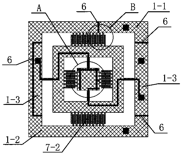
[0043] Such as image 3 As shown, the outer frame 1 of this embodiment is divided into an outer frame measuring part 1 - 1 , an outer frame driving part 1 - 2 and an outer frame connecting part 1 - 3 by a plurality of outer frame isolation grooves 6 . The difference from Example 1 is that, if Figure 5 As shown, an outer frame isolation groove 6 of this embodiment is located at the position of the fixed teeth on one side of the outer frame 1, and the outer frame isolation groove 6 divides one side of the outer frame 1 into an outer frame measuring part 1-1 and an outer frame driving part 1-2, where the inner side of the outer frame measuring part 1-1 is connected to some static teeth, and the fixed teeth of this part and the movable teeth corresponding to the inner frame 2 form the outer feedback comb group 7-1; the inner side of the outer frame driving part 1-2 is connected to another A part of the static teeth and the movable teeth corresponding to the inner frame 2 form th...
Embodiment 3
[0048] Such as Figure 6 As shown, the mirror isolation groove 8 on the left side of the mirror 3 in this embodiment is the same as the first embodiment, and divides the mirror 3 into a mirror driving part 3-2 and a central part 3-3. The mirror isolation groove 8 on the right runs through the entire mirror surface, and the right side contains two branch isolation grooves, which are double T-shaped structures, and the right side of the mirror surface 3 is divided into three parts, the upper, middle and lower parts, which are the upper mirror driving part 3-2, The middle mirror feedback part 3-1 and the lower mirror driving part 3-2. The two mirror driving parts 3-2 are connected to part of the comb teeth on the right side of the mirror surface 3, and this part of the comb teeth is used as a movable tooth corresponding to the fixed teeth of the inner frame 2 to form an inner drive comb tooth group 9-2, and the mirror surface feedback part 3-1 Connected with the middle comb, the...
PUM
 Abstract
Description
Claims
Application Information