
Negative oxygen ion emission window

A technology of negative oxygen ions and emission windows, which is applied to electrical components, circuits, corona discharge devices, etc., can solve the problems of inconvenient cleaning of emission window panels, reduction in the number of negative ions, and inability to effectively emit them. Cost and assembly cost reduction, and the effect of easy scrubbing and cleaning

Pending Publication Date: 2020-01-17
ZHEJIANG YIDONG ENVIRONMENTAL TECH LTD
View PDF0 Cites 0 Cited by
  • Summary
  • Abstract
  • Description
  • Claims
  • Application Information

AI Technical Summary

Problems solved by technology

[0003] The existing typical structure mainly has the following disadvantages: the gold needle of the gold needle emission component is built in, and the tip of the gold needle is 5-10mm away from the surface of the emission window plate, a considerable part of the negative ions emitted is absorbed by the inner surface, and the amount of negative ions emitted to the outside is relatively reduced; due to the high-voltage negative ions It has an adsorption effect on dust in the air. After using for a period of time, a layer of dust and dirt will be absorbed around the gold needle and the surface of the emission window. Since the gold needle assembly is built-in, it is very inconvenient to clean through the emission window, especially the inner surface cannot be cleaned. , the inner surface will form a conductive layer of dust, these conductive layers will first capture the negative ions in the air, so that the number of negative ions emitted outside will be reduced
In this way, the emission effect will gradually weaken, and even the situation that it cannot be effectively emitted will appear.

Method used


Image

  • Negative oxygen ion emission window
  • Negative oxygen ion emission window
  • Negative oxygen ion emission window

Examples


Embodiment Construction

[0028] The following will clearly and completely describe the technical solutions in the embodiments of the present invention with reference to the accompanying drawings in the embodiments of the present invention. Obviously, the described embodiments are only some, not all, embodiments of the present invention. Based on the embodiments of the present invention, all other embodiments obtained by persons of ordinary skill in the art without making creative efforts belong to the protection scope of the present invention.

[0029] The object of the present invention is to provide a negative oxygen ion emission window to solve the problems in the prior art, so that the tip of the emission gold needle is exposed, the negative ion emission effect is better and the cleaning is convenient.

[0030] In order to make the above objects, features and advantages of the present invention more comprehensible, the present invention will be further described in detail below in conjunction with ...


PUM


Abstract

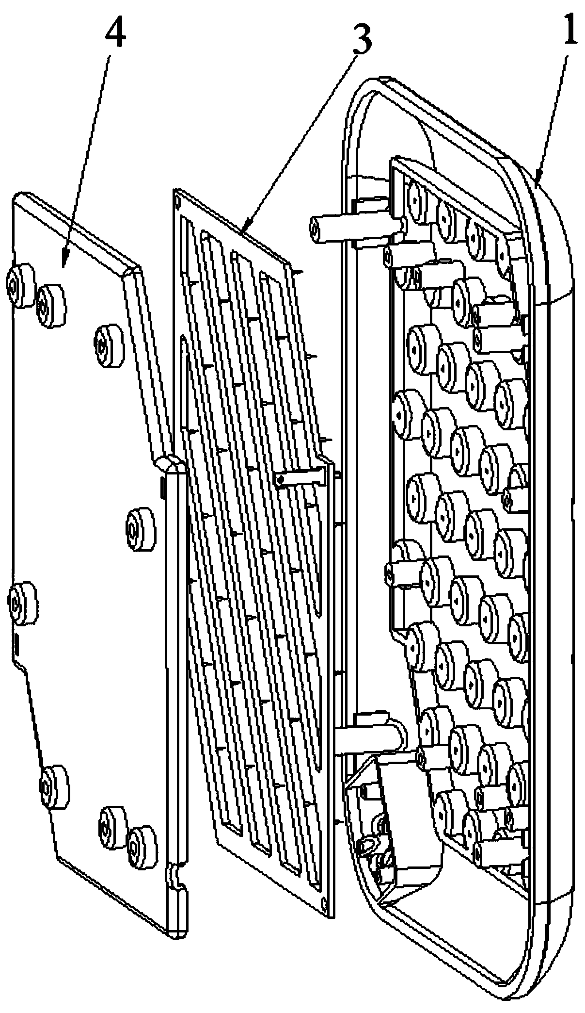
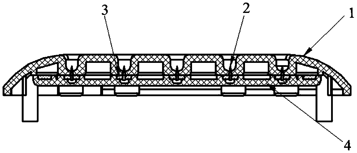
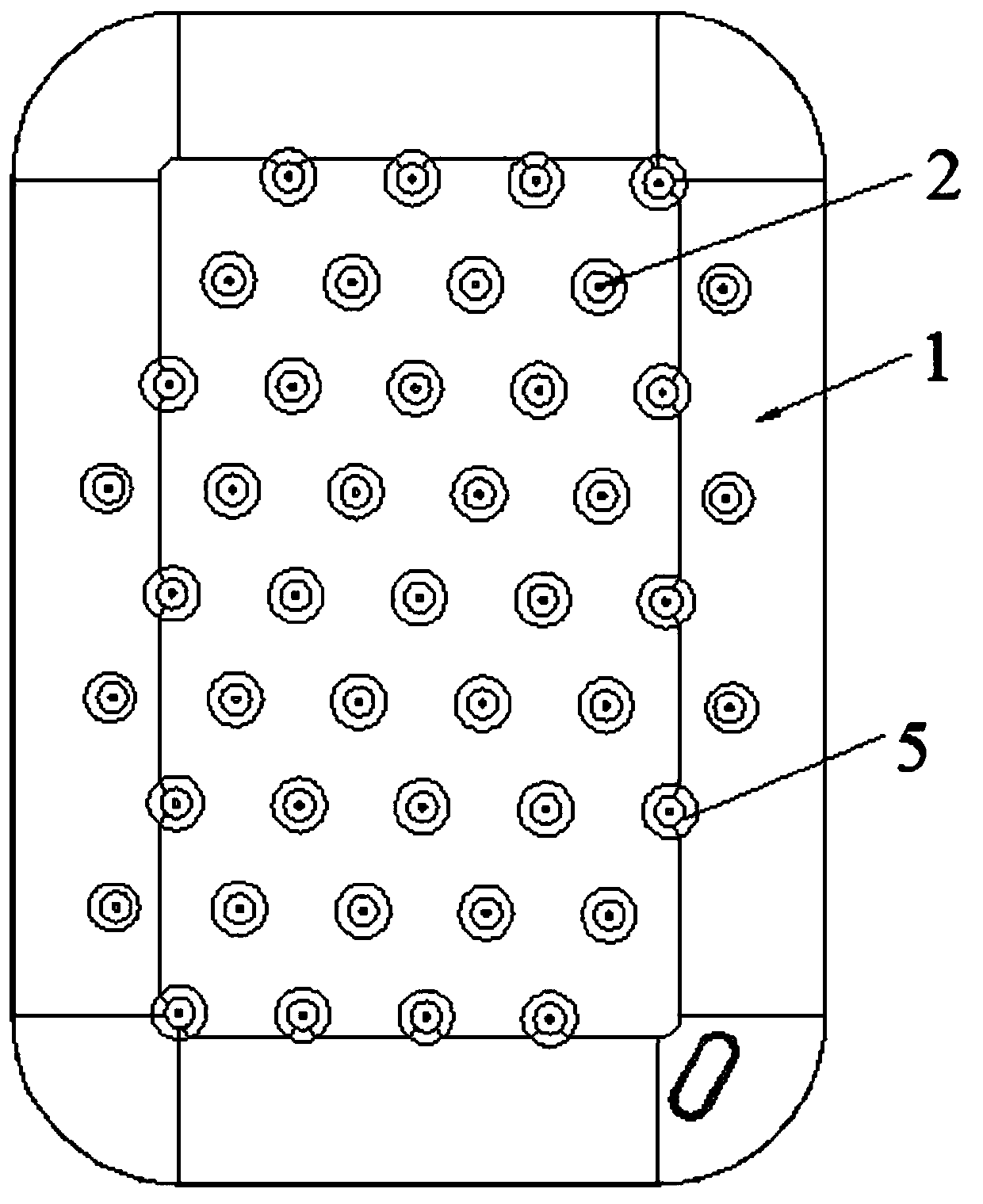
The invention discloses a negative oxygen ion emission window which comprises an emission window plate, a gold needle assembly and an insulation fixing plate. A concave part is arranged on the emission window plate, a gold needle of the gold needle assembly is arranged on the emission window plate in a penetrating manner, and the gold needle is higher than the concave part. The gold needle assembly is arranged between the insulation fixing plate and the emission window plate, and the insulation fixing plate is detachably connected with the emission window plate. The gold needle assembly is embedded in the insulation fixing plate, the insulation fixing plate is connected with the emission window plate through a bolt, and the bolt penetrates through the gold needle assembly. According to a nest-shaped structure and the groove-shaped structure gold needle emission window plate, the tip of the emission gold needle is exposed, the space at the front end of the needle tip is not blocked, negative ions do not have the inner surface absorption, and a negative ion emission effect is better. After the negative oxygen ion emission window is used for a period of time, even if dust and dirt areadsorbed on the needle tip and at the periphery, the outer surface is very convenient to scrub and clean, and the emission effect is not influenced. The space structure is further reduced by adoptingshort gold needles, the overall size of the product is reduced, the product structure is simplified, and the cost is reduced.

Description

technical field [0001] The invention relates to the technical field of negative oxygen ion emission equipment, in particular to a negative oxygen ion emission window. Background technique [0002] In the existing typical gold needle emission structure, the gold needle emission assembly is installed behind the emission window plate, and the tip of the emission gold needle is 5-10mm away from the outer surface of the emission window. The emission window has a grid or mesh structure to facilitate the emission of negative ions. Because the golden needles are inside the machine, in order to reduce the accumulation of negative ions inside the machine, a fan and air duct structure are generally installed behind the golden needle assembly to form an outward air flow to bring out the negative ions. attached Figure 9 and 10 It is a typical gold needle component structure, using long gold needles (length 15-18mm), the gold needle points are connected in series through the gold needle...

Claims


Application Information

Patent Timeline
IPC IPC(8): H01T19/04H01T23/00
CPCH01T19/04H01T23/00
Inventor 许加元黎洪琦
Owner ZHEJIANG YIDONG ENVIRONMENTAL TECH LTD
Learn More